A positive displacement flow meter is a cyclic mechanism built to pass a fixed volume of fluid through with every cycle. Every cycle of the meter’s mechanism displaces a precisely defined (“positive”) quantity of fluid, so that a count of the number of mechanism cycles yields a precise quantity for the total fluid volume passed through the flow meter.
Many positive displacement flow meters are rotary in nature, meaning each shaft revolution represents a certain volume of fluid has passed through the meter.
Some positive displacement flow meters use pistons, bellows, or expandable bags working on an alternating fill/dump cycle to measure discrete fluid quantities.
Positive displacement flow meters have been the traditional choice for residential and commercial natural gas flow and water flow measurement in the United States (a simple application of custody transfer flow measurement, where the fluid being measured is a commodity bought and sold).
The cyclic nature of a positive displacement meter lends itself well to total gas quantity measurement (and not just flow rate), as the mechanism may be coupled to a mechanical counter which is read by utility personnel on a monthly basis.
Positive Displacement Flow Meter
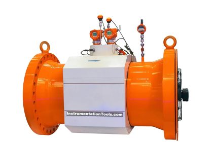
A rotary gas flow meter is shown in the following photograph. Note the odometer-style numerical display on the left-hand end of the meter, totalizing gas usage over time:

Positive displacement flow meters rely on moving parts to shuttle quantities of fluid through them, and these moving parts must effectively seal against each other to prevent leakage past the mechanism (which will result in the instrument indicating less fluid passing through than there actually is).
In fact, the defining characteristic of any positive displacement device is that fluid cannot move through without actuating the mechanism, and that the mechanism cannot move
without fluid passing through. This stands in contrast to machines such as centrifugal pumps and turbines, where it is possible for the moving part (the impeller or turbine wheel) to jam in place and still have fluid pass through the mechanism. If a positive displacement mechanism jams, fluid flow absolutely halts.
Also Read : Types of Positive displacement flow meters
The finely-machined mechanical components of a positive displacement flow meter will suffer damage from grit or other abrasive materials present in the fluid, which means these flow meters are applicable only to clean fluid flow streams.
Even with clean fluid flowing through, the sealing surfaces of the mechanisms are subject to wear and accumulating inaccuracies over time.
However, there is really nothing more definitive for measuring volumetric flow rate than an instrument built to measure individual volumes of fluid with each mechanical cycle.
As one might guess, these instruments are completely immune to swirl and other large-scale fluid turbulence, and may be installed nearly anywhere in a piping system (no need for long sections of straight-length pipe upstream or downstream).
Positive displacement flowmeters are also very linear, since mechanism cycles are directly proportional to fluid volume.
A large positive displacement flowmeter used to measure the flow of liquid (registering total accumulated volume in units of gallons) is shown here, having been cut away for use as an instructional display:

The left-hand photograph shows the gear mechanism used to convert rotor motion into a visible total readout.
The right-hand photograph shows a close-up of the interlocking rotors (one with three lobes, the other with four slots which those lobes mesh with).
Both the lobes and slots are spiral-shaped, such that fluid passing along the spiral pathways must “push” the lobes out of the slots and cause the rotors to rotate.
So long as there is no leakage between rotor lobes and slots, rotor turns will have a precise relationship to fluid volume passed through the flow meter.
If you liked this article, then please subscribe to our YouTube Channel for Instrumentation, Electrical, PLC, and SCADA video tutorials.
You can also follow us on Facebook and Twitter to receive daily updates.
Read Next:
- Flow Meter Pressure Relation
- What is Mass Flow Meters
- Paddle wheel flow meters
- Turbine Flow Meters Tips
- Ultrasonic Flow meter Animation


Interestingly the first positive displacement meters were for gas utility metering, i.e.transaction meters. The first positive displacement meter for liquids didn’t arrive till the Kennedy Reciprocating Piston meter patented in 1824. This consisted of a single piston rising and falling in a vertical cylinder and linked to a 4 way changeover valve. It was intended as a utility water meter and became the benchmark for nearly 140 years as such and though many other positive displacement meters were designed and improved designs of the reciprocating piston, none was successful in displacing it from water metering.
Ove the years many variants were produced such as the Worthington twin piston design in the 1850s, , Manchester meters in the 1860, another from Tylors in the 1880s.
There was also, for water, a three piston design. Four piston designs are common today for lube oils and low flows. I think Beck meters even had a five piston design.
While most were water meters before the 20th century, some became the basis for fuel meters in the 20th.
One might suggests that they are the most perfect positive displacement meters and positive displacement the most perfect of all technologies for flow measurement,. Today their niche, if it can be called a niche, is in petrol and diesel metering when fueling vehicles, and they have proven very resistant to the encroachment of the modern static meters like multi chord ultrasonic or coriolis.
Positive displacement is the most perfect of all technologies because the swept volume, the volume that produces one complete cycle, is dependent entirely on the geometry of the meter and no other factor. This means that in theory they should deliver perfect accuracy and linearity at any achievable flow rate between zero and infinity. Many meters include working clearances which can result in slip flow and slip flow does vary with the slip flow path and with headloss or flow rate.
Anything that affects the performance, accuracy or linearity etc., does so only through the effect on slip flow. Some meters, like reciprocating piston which uses flexible seals between the piston(s) and cylinder(s) exhibit minimal slip flow and thus minimal variation on overall performance.
The least well performing PD meters typically deliver +/-o.1% of reading accuracy over something like a 100:1 turndown. One of the most accurate is said to be the Brooks Birotor. This employs the principle patented by IMO (Sweden) in 1934…. as a water meter (made under license by Pittsburgh Meter Company in 1939 and an example in the Smithsonian). One user claimed to have proved it at +/- 0.01% of reading though he didn’t say over what flow range. The slip flow in this meter is not due to any seals but due to the sequence of clearances making slip flow very very minimal.
Note that the positive displacement principle is so good it is used to calibrate all types of meter. In fiscal metering we have the ball and piston provers, in gas metering the Bell Prover is another use and for very low flows of liquids and gases we have the flying meniscus and flying bubble methods.