Inst ToolsInst ToolsInst Tools
  • Courses
  • Automation
    • PLC
    • Control System
    • Safety System
    • Communication
    • Fire & Gas System
  • Instrumentation
    • Design
    • Pressure
    • Temperature
    • Flow
    • Level
    • Vibration
    • Analyzer
    • Control Valve
    • Switch
    • Calibration
    • Erection & Commissioning
  • Interview
    • Instrumentation
    • Electrical
    • Electronics
    • Practical
  • Q&A
    • Instrumentation
    • Control System
    • Electrical
    • Electronics
    • Analog Electronics
    • Digital Electronics
    • Power Electronics
    • Microprocessor
  • Request
Search
  • Books
  • Software
  • Projects
  • Process
  • Tools
  • Basics
  • Formula
  • Power Plant
  • Root Cause Analysis
  • Electrical Basics
  • Animation
  • Standards
  • 4-20 mA Course
  • Siemens PLC Course
Reading: What is Globe Valve ?
Share
Notification Show More
Font ResizerAa
Inst ToolsInst Tools
Font ResizerAa
  • Courses
  • Design
  • PLC
  • Interview
  • Control System
Search
  • Courses
  • Automation
    • PLC
    • Control System
    • Safety System
    • Communication
    • Fire & Gas System
  • Instrumentation
    • Design
    • Pressure
    • Temperature
    • Flow
    • Level
    • Vibration
    • Analyzer
    • Control Valve
    • Switch
    • Calibration
    • Erection & Commissioning
  • Interview
    • Instrumentation
    • Electrical
    • Electronics
    • Practical
  • Q&A
    • Instrumentation
    • Control System
    • Electrical
    • Electronics
    • Analog Electronics
    • Digital Electronics
    • Power Electronics
    • Microprocessor
  • Request
Follow US
All rights reserved. Reproduction in whole or in part without written permission is prohibited.
Inst Tools > Blog > Control Valves > What is Globe Valve ?

What is Globe Valve ?

Last updated: January 8, 2019 1:53 pm
Editorial Staff
Control Valves
No Comments
Share
3 Min Read
SHARE

A globe valve is a linear motion valve used to stop, start, and regulate fluid flow.

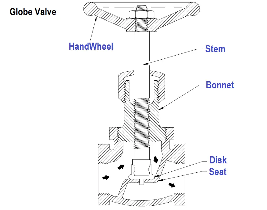
A Z-body globe valve is illustrated in below Figure. The globe valve disk can be totally removed from the flowpath or it can completely close the flowpath.

The essential principle of globe valve operation is the perpendicular movement of the disk away from the seat.

Globe Valve Parts

Figure : Z-Body Globe Valve

This causes the annular space between the disk and seat ring to gradually close as the valve is closed. This characteristic gives the globe valve good throttling ability, which permits its use in regulating flow.

Therefore, the globe valve may be used for both stopping and starting fluid flow and for regulating flow.

When compared to a gate valve, a globe valve generally yields much less seat leakage. This is because the disk-to-seat ring contact is more at right angles, which permits the force of closing to tightly seat the disk.

Globe valves can be arranged so that the disk closes against or in the same direction of fluid flow. When the disk closes against the direction of flow, the kinetic energy of the fluid impedes closing but aids opening of the valve.

When the disk closes in the same direction of flow, the kinetic energy of the fluid aids closing but impedes opening. This characteristic is preferable to other designs when quick-acting stop valves are necessary.

Globe valves also have drawbacks. The most evident shortcoming of the simple globe valve is the high head loss from two or more right angle turns of flowing fluid.

Obstructions and discontinuities in the flowpath lead to head loss. In a large high pressure line, the fluid dynamic effects from pulsations, impacts, and pressure drops can damage trim, stem packing, and actuators.

In addition, large valve sizes require considerable power to operate and are especially noisy in high pressure applications.

Other drawbacks of globe valves are the large openings necessary for disk assembly, heavier weight than other valves of the same flow rating, and the cantilevered mounting of the disk to the stem.
Articles You May Like :

Basics of Control Valve Sizing

Control Valve Trim Types

Relative Flow Capacity of a Valve

Butterfly Valves Construction

What is Swing Check Valve ?

Don't Miss Our Updates
Be the first to get exclusive content straight to your email.
We promise not to spam you. You can unsubscribe at any time.
Invalid email address
You've successfully subscribed !

Continue Reading

How Sliding Stem Valves Work ?
Control Valve Recommended Practices for Harsh Process Conditions
Basics of Globe Valves
Globe Valve Body Design
Valve Terminology Glossary
Types of Control Valves
Share This Article
Facebook Whatsapp Whatsapp LinkedIn Copy Link
Share
Leave a Comment

Leave a Reply Cancel reply

Your email address will not be published. Required fields are marked *

Stay Connected

128.3kFollowersLike
69.1kFollowersFollow
210kSubscribersSubscribe
38kFollowersFollow

Categories

Explore More

Valve Position Indication
Interview Questions on Control Valves
Control Valves Leakage Classifications
Solenoid Actuated Valves
Globe Valve Seat and Disk
Solenoid Valve Problems and Solutions
What is Gate Valve ?
3 Port 2 Position Direct Acting Solenoid Valve Working Principle

Keep Learning

Level Control Valve with Horizontal Float

Level Control Valve with Horizontal Float

Difference between Globe Valve and Gate Valve

Difference between Globe Valve and Gate Valve ?

Air Cylinder Consumption Calculation for Control Valves

Air Cylinder Consumption Calculation for Control Valves

Working of Shuttle valve

What is a Shuttle Valve? Principle, Advantages, Disadvantages

Erratic Stroking Control Valves

Erratic Stroking Control Valves Delaying the Shutdown Plant Restart

Air Pressure Regulator cut-away diagram

Air Pressure Regulator Questions

gate-valve-principle-animation

Basics of Gate Valves

Valve Seat leakage Test

Valve Seat Leakage Test

Learn More

Power Systems Questions & Answers

Power Systems MCQ Series 10

Radiation Exposure Converter

Free Online Radiation Exposure Calculating Platform

Heat Detector Testing Procedure

Heat Detector Testing Procedure

Difference Between Passive and Active Fire Protection

Active and Passive Fire Protection

History of 3-15 psi, 10-50 mA, and 4-20 mA signals

History of 3-15 psi, 10-50 mA, and 4-20 mA signals

What is FAT and SAT?

What is FAT and SAT? Difference between them

Calculate PV Value

Calculate Process Variable from Transmitter Current

PLC Program using Logic GATEs

PLC Logic GATE Program

Menu

  • About
  • Privacy Policy
  • Copyright

Quick Links

  • Learn PLC
  • Helping Hand
  • Part Time Job

YouTube Subscribe

Follow US
All rights reserved. Reproduction in whole or in part without written permission is prohibited.
Welcome Back!

Sign in to your account

Username or Email Address
Password

Lost your password?