Inst ToolsInst ToolsInst Tools
  • Courses
  • Automation
    • PLC
    • Control System
    • Safety System
    • Communication
    • Fire & Gas System
  • Instrumentation
    • Design
    • Pressure
    • Temperature
    • Flow
    • Level
    • Vibration
    • Analyzer
    • Control Valve
    • Switch
    • Calibration
    • Erection & Commissioning
  • Interview
    • Instrumentation
    • Electrical
    • Electronics
    • Practical
  • Q&A
    • Instrumentation
    • Control System
    • Electrical
    • Electronics
    • Analog Electronics
    • Digital Electronics
    • Power Electronics
    • Microprocessor
  • Request
Search
  • Books
  • Software
  • Projects
  • Process
  • Tools
  • Basics
  • Formula
  • Power Plant
  • Root Cause Analysis
  • Electrical Basics
  • Animation
  • Standards
  • 4-20 mA Course
  • Siemens PLC Course
Reading: Valve Interlock
Share
Font ResizerAa
Inst ToolsInst Tools
Font ResizerAa
  • Courses
  • Design
  • PLC
  • Interview
  • Control System
Search
  • Courses
  • Automation
    • PLC
    • Control System
    • Safety System
    • Communication
    • Fire & Gas System
  • Instrumentation
    • Design
    • Pressure
    • Temperature
    • Flow
    • Level
    • Vibration
    • Analyzer
    • Control Valve
    • Switch
    • Calibration
    • Erection & Commissioning
  • Interview
    • Instrumentation
    • Electrical
    • Electronics
    • Practical
  • Q&A
    • Instrumentation
    • Control System
    • Electrical
    • Electronics
    • Analog Electronics
    • Digital Electronics
    • Power Electronics
    • Microprocessor
  • Request
Follow US
All rights reserved. Reproduction in whole or in part without written permission is prohibited.
Inst Tools > Blog > Control Valves > Valve Interlock

Valve Interlock

Last updated: May 25, 2020 10:46 am
Editorial Staff
Control Valves
No Comments
Share
6 Min Read
SHARE

A valve interlock is a trapped key lock assembly which locks the valve in one or two positions – open and/or closed – with one key trapped within the lock assembly and one key free. It’s about controlling the sequence of events, conducting different valve process activities.

Contents
What is a key interlock?Valve Interlock System

To change the valve position (open-to-close or close-to-open), two keys need to be inserted into the lock assembly. The free key can only be released when the valve is in the open or closed position. Alternatively, a ‘single keyed interlock’ only allows the removal of the locked open or closed key when the valve is in the correct locking position.

Valves play an important role in the safety of operation in many process industries, especially in the chemical and petroleum industry. The opening and closing of valves, especially block valves on PSVs for example, in the wrong sequence can lead to serious consequences such as human fatal injuries, loss of production, and damage of equipment.

Therefore valves critical for the safety of the operations can be equipped with an interlock system to ensure that valves are operated in a safe sequence and maintained in a safe position. The valve interlocks not only control the opening and closing sequence of process valves but also prevent their unauthorized operation.

What is a key interlock?

The types of interlock systems are based on the principle of key exchange or a key transfer principle. Valves can only be operated in a predetermined sequence which is designed to maintain production, availability, and the safety of systems.

Key interlocks are integral-fit mechanical locking devices, attached to the host equipment. Typical interlock systems are applied to valves, closure doors, rotary switches, or any form of equipment operated by human intervention. In addition, keys can be customized to intelligent format: electronic tagging of individual keys and managed by system software.

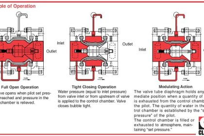
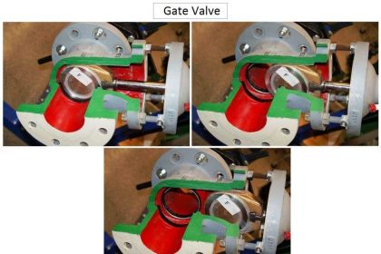
The lock mechanism is designed to ensure that valves are always either fully open or fully closed. Generally, the system is based on the operating principle of one key free when the valve is locked closed and the other key free when the valve is locked open.

Popular Permit to Work (PTW) or Lockout/Tagout procedures provides a lock-off capability. But they don’t provide any control of the sequence of operations or the status of equipment. This can generate dangerous conditions through negligence. Interlocks provide an effective front-line safety tool that mitigates risks of human error.

Valve Interlock System

The type of interlock system below is designed to mechanically interlock two pressure safety valves having two upstream block valves and two downstream block valves to prevent isolation of both the relief valves at the same time and allow safe isolation of the safety valve for maintenance.

Operating condition of the valve interlock

  • One PSV (PSV-A) is operational and another PSV (PSV-B) is standby
  • Key B is taken from the control room

To put PSV-B into maintenance:

  • Insert key B into valve #4 and close by releasing key A
  • Key A can be taken to the control room to keep PSV-B isolated for maintenance

To change-over putting PSV-A into operation and PSV-B into operation:

  • Insert key B into valve #1 and open by releasing key C (both safeties are online)
  • Insert key C into valve #2 and close by releasing key D, which can be taken to the control room

PSV-B is now in operation and PSV-A is in standby. 

To further isolate PSV-A for maintenance:

  • Insert key D into valve #3 and close releasing key E
  • Key E can be taken to the control room to keep PSV-A isolated for maintenance

Both PSVs will never be closed simultaneously, ensuring that at least one PSV is always available for equipment protection.

Valve Interlock

Valve interlocks are used everywhere where a sequence of valves helps protect personnel and machinery.

Valves have a very important safety function in many industrial processes. An operating error at a valve can have dramatic consequences – personal injuries, damages to the plant, or even contamination of the environment can be a result. Thus, the safe operation of valves must be guaranteed. By using the Valve interlocks you can be sure the correct sequence of operating procedures will always be adhered to.

Source:

  • alcatrazinterlocks
  • haake-technik

Read Next:

  • Questions & Answers on Valves
  • Valve Air Cylinder Calculation
  • Control Valve Stroke Test 
  • 5 Valve Manifold Operation
  • How does Needle Valve work?
Don't Miss Our Updates
Be the first to get exclusive content straight to your email.
We promise not to spam you. You can unsubscribe at any time.
Invalid email address
You've successfully subscribed !

Continue Reading

Control Valve End Connection
Inherent vs Installed Control Valve Flow Characteristics
Diaphragm Valves Construction, Types, Stem & Bonnet Assembly
Control Valve Positioners
Disassembly of Sliding-stem Control Valve
Interview Questions on Control Valves
Share This Article
Facebook Whatsapp Whatsapp LinkedIn Copy Link
Share
Leave a Comment

Leave a Reply Cancel reply

Your email address will not be published. Required fields are marked *

Stay Connected

128.3kFollowersLike
69.1kFollowersFollow
210kSubscribersSubscribe
38kFollowersFollow

Categories

Explore More

What is an Altitude Valve?
Basics of Ball Valves
Working Principle of Hydraulic Actuators
Basics of Butterfly Valves
Constant Flow Valve Principle
Types of Valve Actuators
Control Valve Testing for Noise Measurement
Control Valve Performance with Constant Pressure

Keep Learning

Y Body Globe Valve

Globe Valve Body Design

Pneumatic Piping Design and Specification

Pneumatic Piping Design and Specification

control valve sizing problem

Importance of Proper Control Valve Sizing

Direct & reverse actions control valve

Direct Acting Control Valves & Reverse Acting Control Valves

double-pumps unit unloading valves

What is an Unloading Valve? – Types, Principle

Choked Flow of Control Valve

Choked Flow of Control Valves

How to Protect Pumps from Cavitation

How to Protect Pumps from Cavitation? – Reasons, Solutions

Snap Acting Relay Working Principle

Snap Acting Relay Working Principle

Learn More

Induced Draft Cooling Tower

Cooling Tower fan FRP fan blades saves and saves

Differential Pressure Transmitter with 5 Way Manifold Valve

Differential Pressure Transmitter with 5 Way Manifold Valve

Power Electronics Objective Questions

Interconnecting Thyristors Objective Questions and Answers

illumination Multiple Choice Questions and Answers

illumination Multiple Choice Questions and Answers (MCQ)

Infrared Spectrometers Questions & Answers

Infrared Spectrometers Questions & Answers

Top 300 Arduino Projects for Engineering Students

Top 300 Arduino Projects for Engineering Students

PLC program pushbutton switches

PLC Permissive for Motor Control

Temperature Switch Working

Basics of Temperature Switch

Menu

  • About
  • Privacy Policy
  • Copyright

Quick Links

  • Learn PLC
  • Helping Hand
  • Part Time Job

YouTube Subscribe

Follow US
All rights reserved. Reproduction in whole or in part without written permission is prohibited.
Welcome Back!

Sign in to your account

Username or Email Address
Password

Lost your password?