Inst ToolsInst ToolsInst Tools
  • Courses
  • Automation
    • PLC
    • Control System
    • Safety System
    • Communication
    • Fire & Gas System
  • Instrumentation
    • Design
    • Pressure
    • Temperature
    • Flow
    • Level
    • Vibration
    • Analyzer
    • Control Valve
    • Switch
    • Calibration
    • Erection & Commissioning
  • Interview
    • Instrumentation
    • Electrical
    • Electronics
    • Practical
  • Q&A
    • Instrumentation
    • Control System
    • Electrical
    • Electronics
    • Analog Electronics
    • Digital Electronics
    • Power Electronics
    • Microprocessor
  • Request
Search
  • Books
  • Software
  • Projects
  • Process
  • Tools
  • Basics
  • Formula
  • Power Plant
  • Root Cause Analysis
  • Electrical Basics
  • Animation
  • Standards
  • 4-20 mA Course
  • Siemens PLC Course
Reading: Create a User-Defined Function Block in Codesys
Share
Font ResizerAa
Inst ToolsInst Tools
Font ResizerAa
  • Courses
  • Design
  • PLC
  • Interview
  • Control System
Search
  • Courses
  • Automation
    • PLC
    • Control System
    • Safety System
    • Communication
    • Fire & Gas System
  • Instrumentation
    • Design
    • Pressure
    • Temperature
    • Flow
    • Level
    • Vibration
    • Analyzer
    • Control Valve
    • Switch
    • Calibration
    • Erection & Commissioning
  • Interview
    • Instrumentation
    • Electrical
    • Electronics
    • Practical
  • Q&A
    • Instrumentation
    • Control System
    • Electrical
    • Electronics
    • Analog Electronics
    • Digital Electronics
    • Power Electronics
    • Microprocessor
  • Request
Follow US
All rights reserved. Reproduction in whole or in part without written permission is prohibited.
Inst Tools > Blog > PLC Tutorials > Create a User-Defined Function Block in Codesys

Create a User-Defined Function Block in Codesys

Learn how to create a user-defined function block in Codesys to optimize your PLC programming. Reduce coding time and memory usage.

Last updated: September 17, 2024 3:53 pm
Viral Nagda
PLC Tutorials
No Comments
Share
5 Min Read
SHARE

When a PLC programmer wants to create a logic where some part will be repeated many times in the program, then instead of writing it every time, he can create a library which will be the reference. In PLC programming, it is called a function block.

Function block allows the programmer to write the logic only once and then use multiple instances of it to reduce the coding time and memory to a great extent. There is one software tool in industrial automation that is used as a base for many software manufacturers, whose name is Codesys.

In this post, we will see how to create a user-defined function block in Codesys.

User-Defined Function Block in Codesys

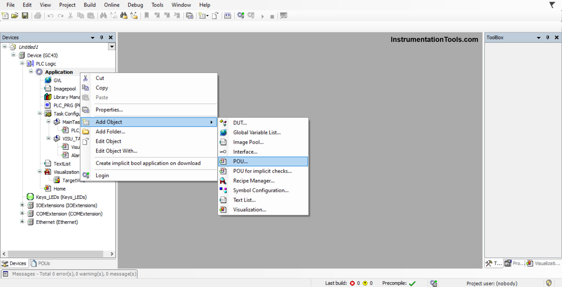
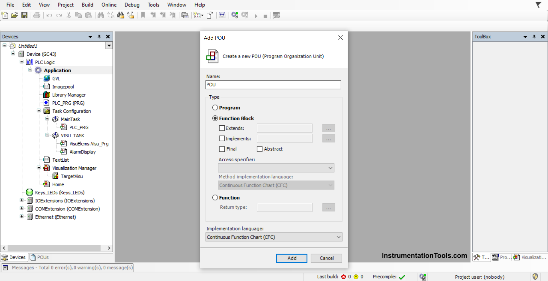
First, in an application, select a new POU as shown in the first image. After that, you will be asked to choose to create a program or a function block.

Create a User-Defined Function Block in Codesys

There, you need to choose the function block as shown in the second image. Choose the corresponding implementation language you require for designing.

Codesys user-defined function block

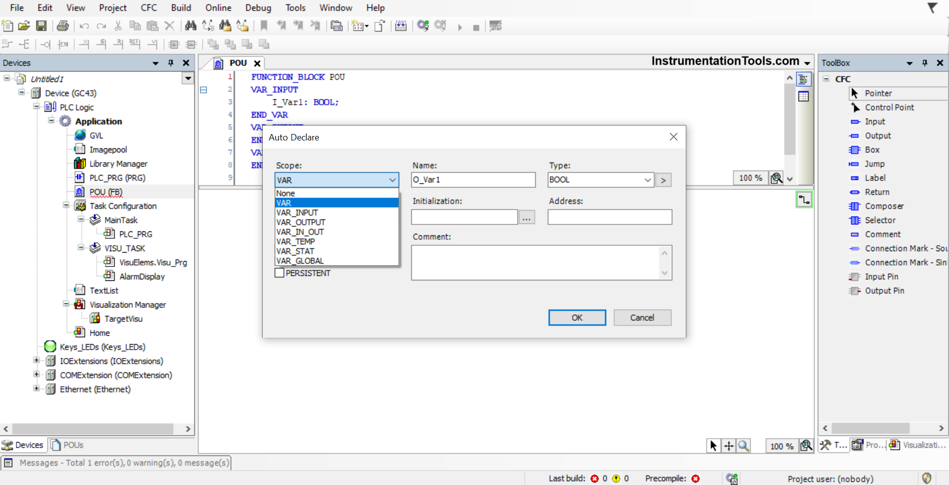
Now, once the function block named POU has been created, you can write the logic inside it. Now, when you mapping a new variable, you will be first asked to create one as shown in the below image.

As a function block requires an input and output, these two types must be used; otherwise, there is no use in creating a function block. This popup comes automatically. Alternatively, you can write and create variables quickly by seeing the second image.

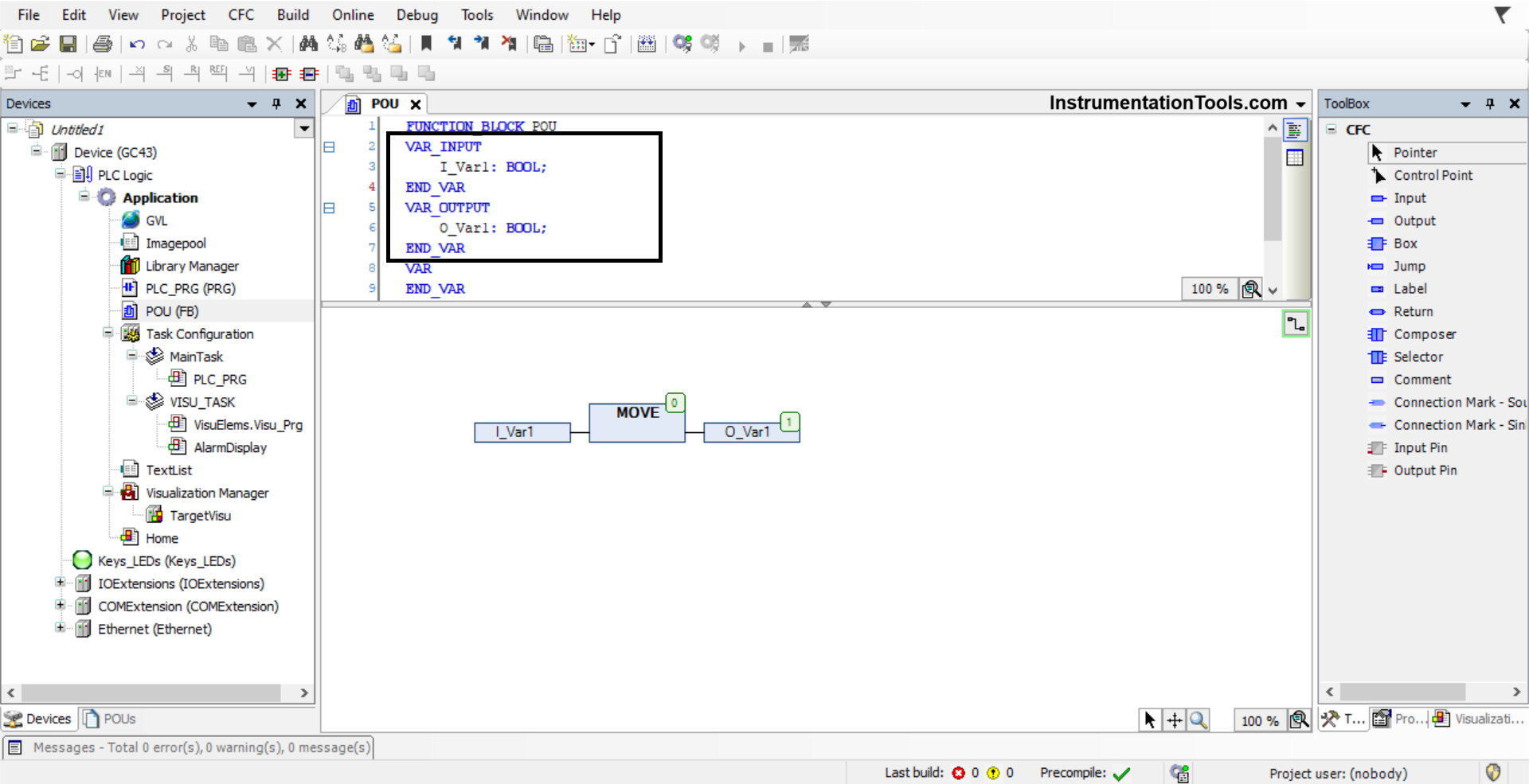
Follow the syntax as shown in a black box and write variables under var_input and var_output. You can also create local variables that can be used just inside the function box, by clicking the var option.

Accordingly, you can design your variable types. You can also make a variable as retentive, by clicking the retain option in the popup shown below.

function block named POU

The logic as of now that has been created is as shown in the second image – the value of the input is being moved to the output.

How to create a function block in Codesys

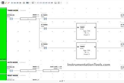
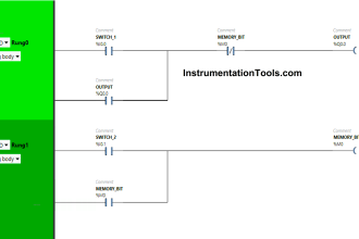
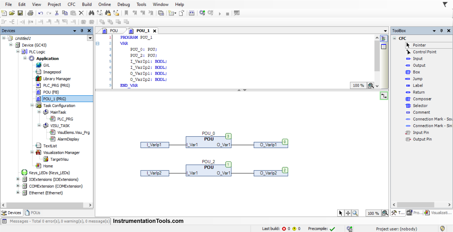
Once the logic inside the function block has been created, you can create a new program and create multiple instances of this function block. As shown in the below image, two instances of the function block have been created.

You can define the variables and blocks locally or globally as per your requirements. We have mapped the input and output variables as shown in the figure. These function blocks work in the same way as a system function block; working independently in instances.

Just remember that the function block instances must not be used more than once, otherwise, the PLC will not realize which function block to execute. And the logic will not work due to this. That is why, as you can see, we have used different names for the two instances we have used.

Function block development in Codesys

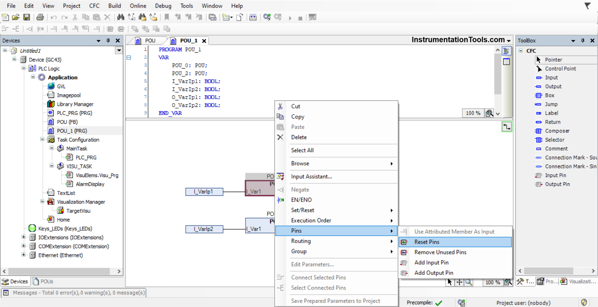
Now, if you make the following changes in the function block – adding or removing some variables, then you update these function block instances by right-clicking the block and using the option reset pin as shown in the below image.

As you can see, you can also remove unused pins (which means input and output), add an input pin, or add an output pin. If you are adding any pin, then you need to make the corresponding changes inside the function block too.

Codesys function block example

In this way, we saw how to create a user-defined function block in the Codesys platform.

Read Next:

  • Vijeo Designer software Import and Export
  • Why different PLC Programming Languages?
  • Download Free HMI software CODESYS
  • What is CODESYS? Why Do You Need to Learn it?
  • Import PlantPAx Add-On Instruction in Studio 5000
Don't Miss Our Updates
Be the first to get exclusive content straight to your email.
We promise not to spam you. You can unsubscribe at any time.
Invalid email address
You've successfully subscribed !

Continue Reading

Lamp Control using PLC Logic Condition
PLC Program for Star Delta Motor Starter
Relay Operation, Types, Symbols & Characteristics
What are Trends in SCADA?
DeMorgan’s Theorems using Ladder Diagram
PLC Program for Paint Spraying
Share This Article
Facebook Whatsapp Whatsapp LinkedIn Copy Link
Share
Leave a Comment

Leave a Reply Cancel reply

Your email address will not be published. Required fields are marked *

Stay Connected

128.3kFollowersLike
69.1kFollowersFollow
210kSubscribersSubscribe
38kFollowersFollow

Categories

Explore More

Contactor – Basics, Wiring, Connection with PLC
What is Fail-safe in Siemens PLC?
Down Counter PLC Program
Rules for Writing SCL Language in Tia Portal
PLC Multiple Outputs Configuration
Studio 5000 Tutorial: PLC Programming for Digital Alarms
How to Read an Electrical Wiring Diagram?
Water Fountain Control Logic – PLC Exercises and Solutions

Keep Learning

SCADA

Top 100+ SCADA Questions

Functional block diagram for analog alarms

PLC Logic for Analog Alarms using Functional Block Diagram

PLC Structured Text Program for Light Sequences via Timers

PLC Structured Text Program for Light Sequences via Timers

Network Switch

Network Switch Port Allocation Details

Automatic Car Door Simulation

Automatic Door Operation PLC Programming and Simulation

Introduction to GOC controllers

Mitsubishi Electric GOC Controllers

TON Timer in RSlogix

Why is RTO used in the Place of TON Timer?

Free Download SCADA Softwares

Free SCADA Software Download

Learn More

Working of Woodward Governor 505

Overview of Woodward Governor 505

ICS System Design

ICS System Design Considerations

Digital Electronics MCQ

Sum of Products & Products of Sum Objective Questions

DP type Flow Transmitter Calibration

DP type Flow Transmitter Preventive Maintenance and Calibration

Differential Pressure Measurement across Baghouse

Differential Pressure Measurement across Baghouse

NH3 Plant Turbo-compressor Sudden Rise in Temperature

NH3 Plant Turbo-compressor Sudden Rise in Temperature

Modbus

Modbus : History, Structure, Modes, Addressing, Functions

Calculate Power in Parallel RC Circuit

Calculate Power in Parallel RC Circuit

Menu

  • About
  • Privacy Policy
  • Copyright

Quick Links

  • Learn PLC
  • Helping Hand
  • Part Time Job

YouTube Subscribe

Follow US
All rights reserved. Reproduction in whole or in part without written permission is prohibited.
Welcome Back!

Sign in to your account

Username or Email Address
Password

Lost your password?