Inst ToolsInst ToolsInst Tools
  • Courses
  • Automation
    • PLC
    • Control System
    • Safety System
    • Communication
    • Fire & Gas System
  • Instrumentation
    • Design
    • Pressure
    • Temperature
    • Flow
    • Level
    • Vibration
    • Analyzer
    • Control Valve
    • Switch
    • Calibration
    • Erection & Commissioning
  • Interview
    • Instrumentation
    • Electrical
    • Electronics
    • Practical
  • Q&A
    • Instrumentation
    • Control System
    • Electrical
    • Electronics
    • Analog Electronics
    • Digital Electronics
    • Power Electronics
    • Microprocessor
  • Request
Search
  • Books
  • Software
  • Projects
  • Process
  • Tools
  • Basics
  • Formula
  • Power Plant
  • Root Cause Analysis
  • Electrical Basics
  • Animation
  • Standards
  • 4-20 mA Course
  • Siemens PLC Course
Reading: Types of IGBT
Share
Font ResizerAa
Inst ToolsInst Tools
Font ResizerAa
  • Courses
  • Design
  • PLC
  • Interview
  • Control System
Search
  • Courses
  • Automation
    • PLC
    • Control System
    • Safety System
    • Communication
    • Fire & Gas System
  • Instrumentation
    • Design
    • Pressure
    • Temperature
    • Flow
    • Level
    • Vibration
    • Analyzer
    • Control Valve
    • Switch
    • Calibration
    • Erection & Commissioning
  • Interview
    • Instrumentation
    • Electrical
    • Electronics
    • Practical
  • Q&A
    • Instrumentation
    • Control System
    • Electrical
    • Electronics
    • Analog Electronics
    • Digital Electronics
    • Power Electronics
    • Microprocessor
  • Request
Follow US
All rights reserved. Reproduction in whole or in part without written permission is prohibited.
Inst Tools > Blog > Power Electronics > Types of IGBT

Types of IGBT

Last updated: September 19, 2016 4:12 am
Editorial Staff
Power Electronics
No Comments
Share
2 Min Read
SHARE

Insulated Gate Bipolar Junction Transistor (IGBTs) are normally classified into two types.

They are namely

(i) Non Punch Through IGBT [NPT-IGBT]igbt-symbol
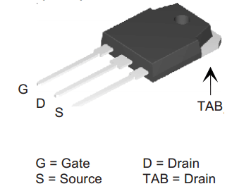
(ii) Punch Through [PT-IGBT].

  • These IGBTs are also referred to as symmetrical and asymmetrical IGBTs.
  • These varieties of IGBT differ widely with regard to their fabrication technology, structural details etc.
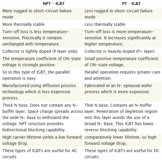
  • The table given below shows the salient features of the two types of IGBT.
  • Before proceeding further it is strongly recommended to read about Basics of IGBT.

The important facts about IGBT are summarized below ( If you are already familiar with IGBT basics, just skip this paragraph and proceed to next section)

  1. IGBT has the advantage of high current capability of BJT and has the advantage of easy control like MOSFET. Actually this power semiconductor device emerged to overcome the drawback of transistor and mosfet.
  2. It is a three terminal device namely Drain, Source and gate or Emitter, Collecter and base.

What is meant by NPT-IGBT and PT-IGBT?
IGBTs having n+ buffer layer is called Punch Through-IGBT (PT-IGBT) and IGBTs made without this layer is known as Non Punch Through-IGBT (NPT-IGBT).

It is good to know about the structure of this device, for proper understanding of n+ buffer layer.

Why are they called as Symmetrical and Asymmetrical IGBTs?

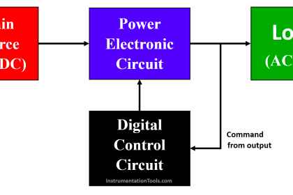
A symmetrical IGBT (NPT-IGBT) is one having equal forward and reverse breakdown voltages. Such devices are used in AC applications.

In the asymmetrical IGBTs (PT-IGBT) structure, the reverse breakdown voltage is less than the forward breakdown voltage. These types of IGBTs are useful for DC circuits where the device is not required to support voltage in the reverse direction.

 Symmetrical and Asymmetrical IGBT

Don't Miss Our Updates
Be the first to get exclusive content straight to your email.
We promise not to spam you. You can unsubscribe at any time.
Invalid email address
You've successfully subscribed !

Continue Reading

How to Test TRIAC with Multimeter
R R-C Firing Circuits Disadvantages
Single-Phase Mid-Point Converter – Bridge Rectifier with Center Tap
Phase Controlled Rectifier – Half Controlled Rectifier with R Load
Turning Off SCR – Commutation
How to test SCR using Multimeter
Share This Article
Facebook Whatsapp Whatsapp LinkedIn Copy Link
Share
Leave a Comment

Leave a Reply Cancel reply

Your email address will not be published. Required fields are marked *

Stay Connected

128.3kFollowersLike
69.1kFollowersFollow
210kSubscribersSubscribe
38kFollowersFollow

Categories

Explore More

MCT (MOS Controlled Thyristor) – Symbol, Working, Characteristics, Advantages
How Snubber Circuit works ?
Phase-Controlled Half-Wave Rectifier With Freewheeling Diode
Thyristor Triggering Circuits – Types, Explanation, Waveforms (SCR)
Power Electronic Devices Specification and Classification
Power Electronics Objective Questions
Power Electronics – Full-wave Rectifier With R and RL Load
Thyristors – Switching, Two Transistor Model, Advantage, Applications

Keep Learning

Static VI Characteristics of Thyristor

Thyristors – Working, VI Characteristics, Turn ON Methods

Power Electronics Projects

Top 100 Power Electronics Projects for Engineering Students

Crowbar fault protection circuit

Crowbar fault protection circuit

Snubber Circuits

Thyristor Protection Circuits (SCR) – Types, Principle, Explanation

RC Triggering

SCR Triggering Methods

SCR Switching Characteristics

SCR Switching Characteristics

Dynamic Characteristics of Power Diode

Power Diode – Characteristics, Construction, Working, Advantages

Basic components of power electronics

What is Power Electronics? Evolution, Block Diagram, Advantages

Learn More

What is Barring Gear Logic? Why is it Required in the Steam Turbine?

Optical Line Terminal

What is an Optical Line Terminal? – OLT Working Principle

Field Instruments Selection Aid

Field Instruments Selection Aid

Difference Between Microcontroller and Microprocessor

Difference Between Microcontroller and Microprocessor

Machine Learning

Difference Between Machine Learning and Artificial Intelligence?

Discrete control system block diagram

Process Control Instrumentation

SMART Transmitters Block Diagram

Smart Transmitters LRV & URV

Things to Take Care of When Designing SCADA System

Things to Take Care of When Designing SCADA System

Menu

  • About
  • Privacy Policy
  • Copyright

Quick Links

  • Learn PLC
  • Helping Hand
  • Part Time Job

YouTube Subscribe

Follow US
All rights reserved. Reproduction in whole or in part without written permission is prohibited.
Welcome Back!

Sign in to your account

Username or Email Address
Password

Lost your password?