This article will discuss how to turn lamps on and off alternately using a flip-flop for set cycles in the PLC with the XG-5000 software. In this program, the lights will turn on alternately with the same time interval, and the timer interval parameters can be adjusted. The lights can be set to turn ON for a specific number of cycles. The system will turn off once the predetermined number of cycles has been reached.
Program Objective
The system can only run if the timer interval parameter and the lamp activation repetition parameter have been set.
Once the system is running, Lamp-A will turn ON first for a specified duration, and after the timer reaches its set time, Lamp-B will turn ON while Lamp-A turns OFF.
When the timer for Lamp-B reaches its set time, Lamp-A will turn ON again, and Lamp-B will turn OFF.
Lamp-A and Lamp-B will alternate turning ON and OFF according to the configured repetition parameter.
The system will use comparison instructions to limit the number of repetitions.
Once the specified number of repetitions has been reached, the system will turn OFF and can only be restarted after the repetition count is reset.
Turn ON Lamps Alternately for Set Cycles
IO Mapping
| S.No. | Comment | Input (I) | Output (Q) | Memory Bit | Memory Word | Timer |
|---|---|---|---|---|---|---|
| 1 | PB_START | P0000 | ||||
| 2 | PB_STOP | P0001 | ||||
| 3 | RESET_COUNTER | P0002 | ||||
| 4 | LAMP_A | P0040 | ||||
| 5 | LAMP_B | P0041 | ||||
| 6 | TIMER_A | T000 | ||||
| 7 | TIMER_B | T001 | ||||
| 8 | SYSTEM_ON | M0000 | ||||
| 9 | IL_COUNTER | M0001 | ||||
| 10 | PV_COUNTER | M100 | ||||
| 11 | SV_TIMER | M101 | ||||
| 12 | SV_COUNTER | M102 |
PLC Programming
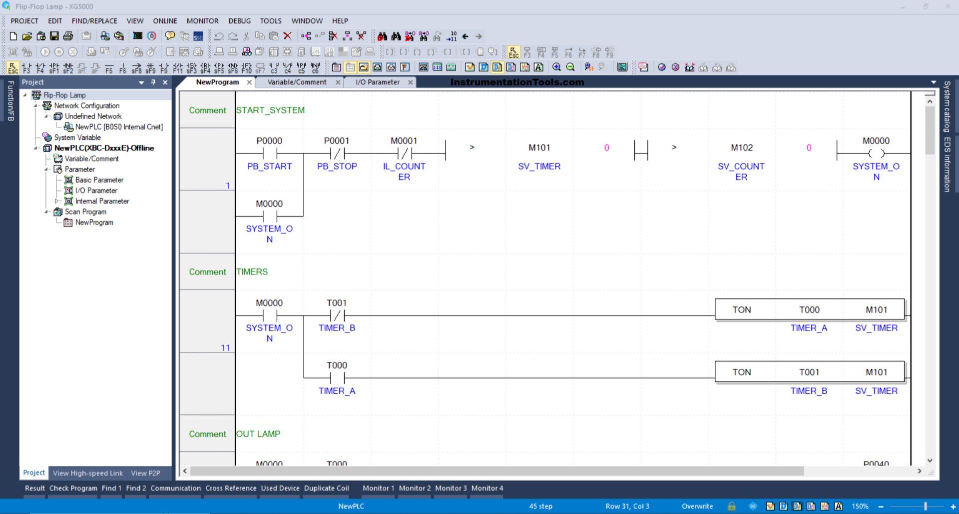
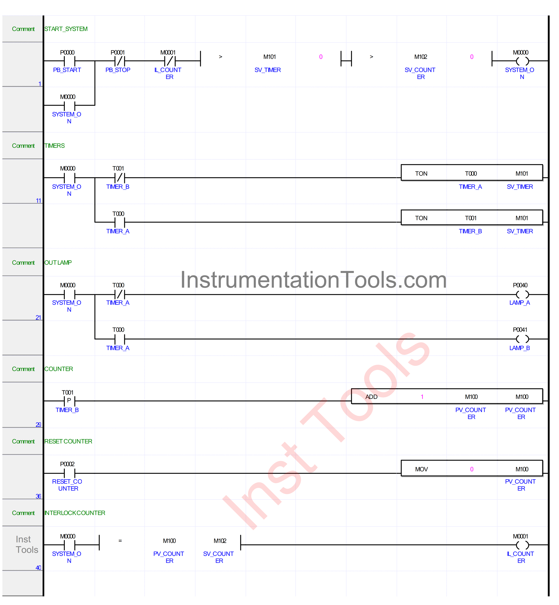
RUNG 1 (START_SYSTEM)
In this Rung, if the PB_START (P0000) button is pressed and the value in the memory word SV_TIMER (M101) and SV_COUNTER (M102) is Greater Than zero “0”, then the memory bit SYSTEM_ON (M0000) will be in the HIGH state. Because it uses Latching, the memory bit SYSTEM_ON (M0000) will remain in the HIGH state even though the PB_START (P0000) button has been released.
The memory bit SYSTEM_ON (M0000) will return to the LOW state if the PB_STOP (P0001) button is pressed or the NC contact of the memory bit IL_COUNTER (M0001) is in the HIGH state.
RUNG 11 (TIMERS)
In this Rung, when the NO contact of the memory bit SYSTEM_ON (M0000) is in the HIGH state, the TIMER_A (T000) timer will start counting with a time period according to the “Set value” that has been given to the memory word SV_TIMER (M101).
Next, after TIMER_A (T000) has finished counting, the TIMER_B (T001) timer will start counting with the same time period as TIMER_A (T000).
After the TIMER_B (T001) timer has finished counting, the TIMER_A (T000) will be OFF due to the Interlock of the TIMER_B (T001) timer. The timer TIMER_B (T001) will also turn off afterward, and the system will repeat again.
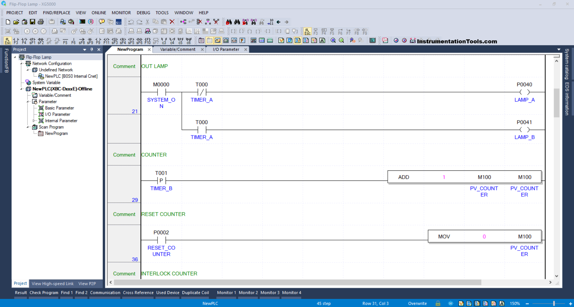
RUNG 21 (OUT LAMP)
In this Rung, if the NO contact of the memory bit SYSTEM_ON (M0000) is in the HIGH state and the NC contact of the timer TIMER_A (T000) is in the LOW state, then the LAMP_A (P0040) output will be ON.
When the NO contact of the timer TIMER_A (T000) is in the HIGH state, then the LAMP_B (P0041) output will be ON.
RUNG 29 (COUNTER)
When the NO contact of the timer TIMER_B (T001) is in the HIGH state, then the value in the memory word PV_COUNTER (M100) will increase (+1). Because it uses the ADD instruction.
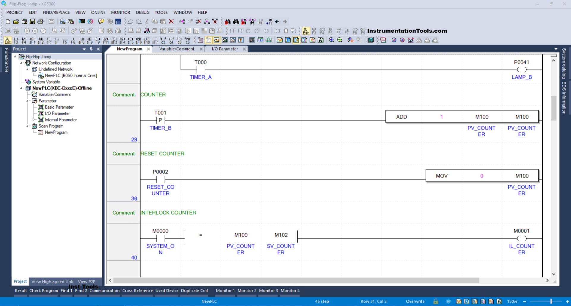
RUNG 36 (RESET COUNTER)
When the RESET_COUNTER (P0002) button is pressed, the value in the memory word PV_COUNTER (M100) will be zero “0”. Because the MOV instruction moves the value “0” to the memory word PV_COUNTER (M100).
RUNG 40 (INTERLOCK COUNTER)
When the NO contact of the memory bit SYSTEM_ON (M0000) is in the HIGH state and the value of the memory word PV_COUNTER (M100) is Equal to SV_COUNTER (M102), the memory bit IL_COUNTER (M0001) will be in the HIGH state.
Read Next:
- PLC Program for Output Circuit with Latched Function
- Traffic Light Auto and Manual Control with PLC Program
- How to Configure Distributed IO in a PLC Programming
- Siemens Communication between PLCs using I-Device
- PLC Programming for Multi-Motor Control for Beginners