Inst ToolsInst ToolsInst Tools
  • Courses
  • Automation
    • PLC
    • Control System
    • Safety System
    • Communication
    • Fire & Gas System
  • Instrumentation
    • Design
    • Pressure
    • Temperature
    • Flow
    • Level
    • Vibration
    • Analyzer
    • Control Valve
    • Switch
    • Calibration
    • Erection & Commissioning
  • Interview
    • Instrumentation
    • Electrical
    • Electronics
    • Practical
  • Q&A
    • Instrumentation
    • Control System
    • Electrical
    • Electronics
    • Analog Electronics
    • Digital Electronics
    • Power Electronics
    • Microprocessor
  • Request
Search
  • Books
  • Software
  • Projects
  • Process
  • Tools
  • Basics
  • Formula
  • Power Plant
  • Root Cause Analysis
  • Electrical Basics
  • Animation
  • Standards
  • 4-20 mA Course
  • Siemens PLC Course
Reading: Troubleshooting Ultrasonic Flow Meter Common Problems
Share
Notification Show More
Font ResizerAa
Inst ToolsInst Tools
Font ResizerAa
  • Courses
  • Design
  • PLC
  • Interview
  • Control System
Search
  • Courses
  • Automation
    • PLC
    • Control System
    • Safety System
    • Communication
    • Fire & Gas System
  • Instrumentation
    • Design
    • Pressure
    • Temperature
    • Flow
    • Level
    • Vibration
    • Analyzer
    • Control Valve
    • Switch
    • Calibration
    • Erection & Commissioning
  • Interview
    • Instrumentation
    • Electrical
    • Electronics
    • Practical
  • Q&A
    • Instrumentation
    • Control System
    • Electrical
    • Electronics
    • Analog Electronics
    • Digital Electronics
    • Power Electronics
    • Microprocessor
  • Request
Follow US
All rights reserved. Reproduction in whole or in part without written permission is prohibited.
Inst Tools > Blog > Flow Measurement > Troubleshooting Ultrasonic Flow Meter Common Problems

Troubleshooting Ultrasonic Flow Meter Common Problems

In this article, we will learn the troubleshooting steps for an ultrasonic type flow meter and their common problems and solutions.

Last updated: February 21, 2023 2:59 pm
Editorial Staff
Flow Measurement
4 Comments
Share
5 Min Read
SHARE

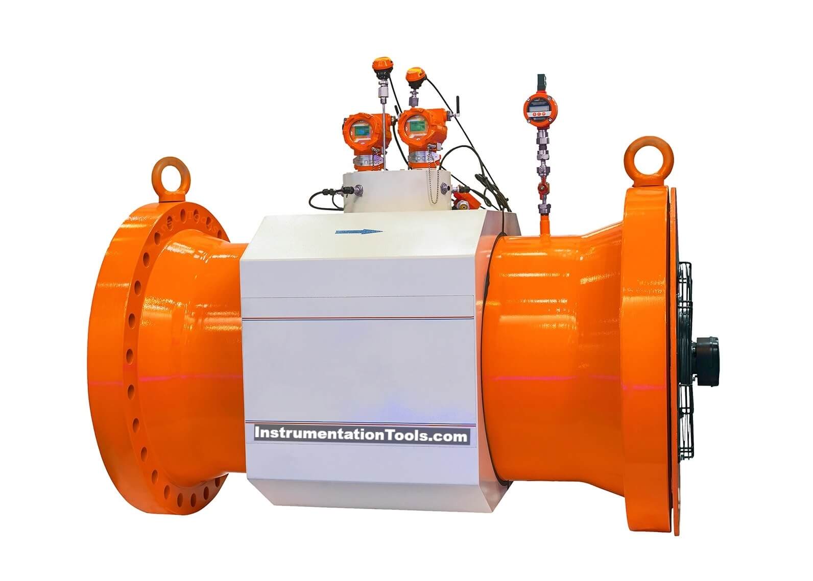
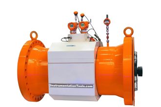
In this article, we will learn the troubleshooting steps for an ultrasonic type flow meter. Like magnetic flow meter, the troubleshooting of the ultrasonic flow meter is also a bit difficult.

Troubleshooting Ultrasonic Flow Meter

Troubleshooting Ultrasonic Flow Meter Common Problems

Follow the below-mentioned steps for troubleshooting an ultrasonic flow meter:

  1. Check the power supply of the ultrasonic flow meter. If power is not present, then check the MCB which is present in the marshalling cabinet or in the power distribution board as per your plant design. If the MCB is found in trip condition, then identify the reason for the tripping. A fuse will also be present in the downstream line of the MCB. Check the fuse’s healthiness also (optional).
  2. If the power is present but the flow meter display is not turning ON, then check the fuse healthiness in the flow meter internal circuit board. If the fuse is okay then check the power supply board status in the flow meter and replace it (or repair it) if it is faulty.
  3. Check all the terminal block connections. The connections should be as per the drawings shown in the vendor manual.
  4. Check the status of the internal cards of the ultrasonic flow meter. The Printed Circuit Board should be clean and without any moisture. Also, the ultrasonic flow meter has internal ribbon-type cables for connecting the cards. Check the ribbon condition also.
  5. For the remote-mounted transmitters, check the connecting cable’s healthiness. Also, check the connections on both sides i.e. on the transmitter as well as on the sensor side.
  6. Check the grounding of the ultrasonic flow meter as per the vendor manual. Since ultrasonic flow meter use millivolts in its circuit, the grounding must be proper.
  7. Some ultrasonic flow meters have functionality in which we can check the noise level. Check the noise level if applicable. Noise should be within acceptable limits as per the vendor guidelines.
  8. If the display is showing values, but the output signal is not getting generated as required, then check the output card status which generates the mA. Connections to the output card can be loose or the output card may be faulty.
  9. If the ultrasonic flow meter does not sense proper values, then check the configurations. All configuration data should be as per the datasheet. Select the proper sensor type as written on the sensor nameplate.
  10. If the display shows a device error or device fault, then replace the amplifier board which is present in the transmitter.
  11. If there is a signal error, then check the signal strength. There is a built-in option for checking signal strength. Verify whether the signal strength is within acceptable limits or not with the signal strength shown in the vendor manual.
  12. You can also connect the laptop with the flow meter and run the software to read the diagnostics information about the flow meter.
  13. If the flow value shown is negative, then check the mounting of the ultrasonic flow meter’s sensor. The mounting may be incorrect. Change the configuration or check the flow direction or correct the sensor mounting direction.
  14. The fluid should be having laminar flow. No solid particle should be present in the fluid.
  15. Ensure the fluid flowing through the flow meter covers the whole pipe.
  16. Remove the sensor from the line. Check for scaling on the electrode. The electrode tip should be clear and should not have any damage.
  17. While cleaning the electrodes, make sure to use a smooth material to clean the electrode. The electrodes are coated with Teflon or some special material depending on the application/fluid type. Hence most care should be taken so that the electrode does not get damaged.
  18. Never calibrate an ultrasonic flow meter in the field and without vendor supervision.

Read Next

  • Electrical Ground Loops
  • Purging of Instruments
  • Purged Impulse Lines
  • Impulse Steam Traps
  • Impulse Piping Installation
Don't Miss Our Updates
Be the first to get exclusive content straight to your email.
We promise not to spam you. You can unsubscribe at any time.
Invalid email address
You've successfully subscribed !

Continue Reading

What is the Purpose of Orifice Plate Drain Hole and Vent Hole?
Flare Ultrasonic Flow Meter – SOPAS Engineering Tool
Types of Vortex Flow Meter Sensors
Mass Flow Calculations
What is a Segmental Wedge Flow Meter?
Importance of Magnetic Flow Meters Grounding
Share This Article
Facebook Whatsapp Whatsapp LinkedIn Copy Link
Share
4 Comments
  • vijay bahadur says:
    August 1, 2022 at 8:08 am

    I found this very informative article. Want to read such more and more

    Reply
    • Saurabh says:
      August 8, 2022 at 11:16 am

      Hi sir

      Reply
  • Ruty says:
    December 9, 2023 at 11:33 am

    This very educative, I like this site for making sure people key into electrical instrumentation study, thanks

    Reply
  • elhadi says:
    August 19, 2024 at 6:37 pm

    sorry I have problem at the oil field the ultrasonic flow meter there is signal at display but no output signal how to solved this problem thanks

    Reply

Leave a Reply Cancel reply

Your email address will not be published. Required fields are marked *

Stay Connected

128.3kFollowersLike
69.1kFollowersFollow
210kSubscribersSubscribe
38kFollowersFollow

Categories

Explore More

Design Considerations of Orifice Plate
Heat Tracing Problems
Important Factors in Flow Measurement
Turbine Flow Meter – Principle, Advantages, Disadvantages
Troubleshooting DP type Transmitter Common Problems
Prover Tank Calibration and Mass Flow Meter Verification Procedure
All About Instrumentation Impulse Lines
Why is Orifice Beta in between 0.3 to 0.7?

Keep Learning

Orifice Flange Rating

Why Orifice Flow Meter Flange is Not Recommended 150# Rating?

Hot wire Anemometer Principle

Hot Wire Anemometer Principle and Types

Turbine Flowmeter Parts

What is a Turbine Flow Meter?

What is a K Factor

Flow Meter K-factor and Calculations

L2F insertion-style flowmeter

Optical Flow Meter Principle

Velocity-based Flowmeter

What is a Velocity-based Flow Meter?

Paddlewheel flowmeter principle

What is a Paddle Wheel Flow Meter?

Magnetic Flow Meters

Magnetic Flow Meters Installation Guidelines

Learn More

Chemical Sensors Objective Questions

Chemical Sensors Objective Questions

Cathode Ray Tube Deflection System

Cathode Ray Tube Deflection System

Feedback control loop - 2

Feedback Control Principle

Optical Level Switch Principle

Optical Level Switch Working Principle

Digital Control Systems

The inverse z-transform & Response of Linear Discrete Systems

Turbine Flowmeter Parts

What is a Turbine Flow Meter?

Power Electronics Objective Questions

Single Phase Voltage Source Inverter MCQ

Electric Bell Working animation

Electric Bell Working animation

Menu

  • About
  • Privacy Policy
  • Copyright

Quick Links

  • Learn PLC
  • Helping Hand
  • Part Time Job

YouTube Subscribe

Follow US
All rights reserved. Reproduction in whole or in part without written permission is prohibited.
Welcome Back!

Sign in to your account

Username or Email Address
Password

Lost your password?