Inst ToolsInst ToolsInst Tools
  • Courses
  • Automation
    • PLC
    • Control System
    • Safety System
    • Communication
    • Fire & Gas System
  • Instrumentation
    • Design
    • Pressure
    • Temperature
    • Flow
    • Level
    • Vibration
    • Analyzer
    • Control Valve
    • Switch
    • Calibration
    • Erection & Commissioning
  • Interview
    • Instrumentation
    • Electrical
    • Electronics
    • Practical
  • Q&A
    • Instrumentation
    • Control System
    • Electrical
    • Electronics
    • Analog Electronics
    • Digital Electronics
    • Power Electronics
    • Microprocessor
  • Request
Search
  • Books
  • Software
  • Projects
  • Process
  • Tools
  • Basics
  • Formula
  • Power Plant
  • Root Cause Analysis
  • Electrical Basics
  • Animation
  • Standards
  • 4-20 mA Course
  • Siemens PLC Course
Reading: Transmitter Turndown Ratio, Set Span and Zero Span
Share
Font ResizerAa
Inst ToolsInst Tools
Font ResizerAa
  • Courses
  • Design
  • PLC
  • Interview
  • Control System
Search
  • Courses
  • Automation
    • PLC
    • Control System
    • Safety System
    • Communication
    • Fire & Gas System
  • Instrumentation
    • Design
    • Pressure
    • Temperature
    • Flow
    • Level
    • Vibration
    • Analyzer
    • Control Valve
    • Switch
    • Calibration
    • Erection & Commissioning
  • Interview
    • Instrumentation
    • Electrical
    • Electronics
    • Practical
  • Q&A
    • Instrumentation
    • Control System
    • Electrical
    • Electronics
    • Analog Electronics
    • Digital Electronics
    • Power Electronics
    • Microprocessor
  • Request
Follow US
All rights reserved. Reproduction in whole or in part without written permission is prohibited.
Inst Tools > Blog > Formulas > Transmitter Turndown Ratio, Set Span and Zero Span

Transmitter Turndown Ratio, Set Span and Zero Span

Last updated: August 1, 2019 5:58 pm
Editorial Staff
Formulas
9 Comments
Share
3 Min Read
SHARE

Explanation of the terms: Transmitter’s Turn down (TD) ratio, set span and zero based span

Consider a Pressure Transmitter and we will discuss some important parameters related to it.

Range :

It is the measurement limit and covers from the minimum to the maximum pressure that the transmitter can measure, e.g., 0 to 5080 mmH2O. The maximum span is 5080 mmH2O.

URL (Upper Range Limit) :

It is the highest pressure at which the transmitter was designed to measure, respected the sensor upper range limit.

LRL (Lower Range Limit) :

It is the lowest pressure at which the transmitter was designed to measure, respected the sensor lower range limit.

URV (Upper Range Value) :

It is the maximum pressure at which the transmitter calibrated.

LRV (Lower Range Value) :

It is the minimum pressure at which the transmitter calibrated.

Span (Range Calibrated) :

It is the work range where the calibration is done is known as span, for example, from 500 to 3000 mmH2O, where the span is 3000-500 = 2500 mmH2O. The Span is equal to URV – LRV.

Turndown(TD) or Rangeability :

It is the relation between the maximum pressure (URL) and the minimum measured pressure (minimum calibrated span). For example, a transmitter range is 0-5080 mmH2O and will be used on 10:1, indicating which transmitter will measure 0 to 508 mmH2O. TD = URL/ Calibrated Span.

Case 1:  

|Lower range value| ≤ |Upper range value|

Field Transmitter Range Calculation

Figure : 1000 mbar (14.5 psi) sensor

Here,

1 : Set span
2 : Zero based span
3 : Nominal value ≅ Upper range limit (URL)
4 : Nominal measuring range
5 : Sensor measuring range

LRL : Lower range limit
URL : Upper range limit
LRV : Lower range value
URV : Upper range value

Example:

Lower range value (LRV) = 0 mbar

Upper range value (URV) = 100 mbar (1.5 psi)

Nominal value (URL) = 1000 mbar (14.5038 psi)

Turn down:

TD = URL /|URV| = 10 : 1

set span:

URV – LRV = 100 mbar (1.5 psi)

This span is based on the zero point.

Case 2:  

|Lower range value| ≥ |Upper range value|

Transmitter Span Range Calculation

Figure : 1000 mbar (14.5 psi) sensor

Example:

Lower range value (LRV) = -300 mbar (-4.5 psi)

Upper range value (URV) = 0 mbar (0 psi)

Nominal value (URL) = 1000 mbar (14.5038 psi)

Turn down:

TD = URL / |LRV| = 3.33 : 1

set span:

URV – LRV = 300 mbar (4.5 psi)

This span is based on the zero point.

Reference : endress hauser

Articles You May Like :

Importance of Turndown Ration

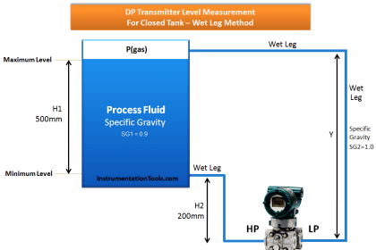
Pressure Transmitter Applications

Smart Transmitter Calibration

DP Transmitter Suppression 

Closed tank DP Level Transmitter

Don't Miss Our Updates
Be the first to get exclusive content straight to your email.
We promise not to spam you. You can unsubscribe at any time.
Invalid email address
You've successfully subscribed !

Continue Reading

How to do 4-20mA Conversions Easily
Formula for Percentage to Process Variable Conversion
Formula for Current 4-20ma to Percentage Conversion
PLC Raw Count Calculation for Pressure Transmitter
Formula for Process Variable to Percentage Conversion
Remote Seal Transmitters Ranging Calculation
Share This Article
Facebook Whatsapp Whatsapp LinkedIn Copy Link
Share
9 Comments
  • Prasenjeet Sen says:
    February 6, 2017 at 3:10 am

    Hi All,

    In the above, please elaborate the effect of Turn Down Ratio of higher or lower during operation or selection of transmitters.

    Reply
    • S Bharadwaj Reddy says:
      February 6, 2017 at 4:17 am

      Hi, Please search the website with word “Turndown” its already there. Thanks

      Reply
  • Kumaresan says:
    September 2, 2017 at 5:51 pm

    Hi , I have certain doubts in case 2
    1. If TD = URL/URV , then it should be 1000/0 as per the formula mentioned

    2. Span = URV – LRV, then it should be 0-(-300), which is 300.
    Please correct me if am wrong

    Reply
    • Faisal says:
      October 7, 2020 at 9:48 am

      Hi Kumaresan:
      In Case 2, we will not use URL/URV to calculate TD, instead we use the absolute LRV.
      This is because the |LRV| is GREATER THAN the |URV|
      (300 > 0)

      Reply
      • T says:
        September 18, 2024 at 7:58 am

        I believe that using the dP where the lrl is -1000 and url is 1000. Then TD is based on 2000, as that is the max span value the transmitter can measure…using the url only works when the transmitter lrl is 0.

        Reply
  • bdboy says:
    August 1, 2019 at 4:37 pm

    Yes !!!! Agree to Kumaresan .I Have the same question.

    Reply
  • Suchita Singh says:
    July 1, 2021 at 11:35 am

    If I need 2.5kg dp transmitter can I use 20 kg dp tx in.place of it.

    Reply
    • More Raghavendra Rao says:
      July 21, 2021 at 3:31 pm

      If your Transmitter is smart type, you can select the range to 2.5Kg/cm2 provided this range meet accuracy requirement

      Reply
  • More Raghavendra Rao says:
    July 21, 2021 at 3:19 pm

    If your DPT is smart type, you can select the range to 2.5Kg/cm2 provided accuracy with in the limit.

    Reply

Leave a Reply Cancel reply

Your email address will not be published. Required fields are marked *

Stay Connected

128.3kFollowersLike
69.1kFollowersFollow
210kSubscribersSubscribe
38kFollowersFollow

Categories

Explore More

PLC Analog Input Conversion Formula
DP Level Transmitter Elevation and Suppression Corrections
Calculate Temperature Coefficient of RTD
Relationship between Temperature Scales
Calculate Control Valve Stem Position
Displacer Level Measurement Calculations
Linear to Square Root Extraction
How to Convert Cable Size from AWG to Inches

Keep Learning

Convert-Linear-%-to-Square-root-%

Formula for Linear % to Square root % conversion

Turbine Flow meter coefficient

Turbine Flow Meter Coefficient and Scaling Factor

Level Calculation with Remote Seals

Level Calculation with Remote Seals

Differential Pressure Transmitter

Calculate Process Variable from 4-20mA using Fraction of Measurement

Kv-value of a valve is determined by a standardised test

Calculate Flow Coefficient Kv of Solenoid Valve

4-20mA Image

4-20mA Graphical Calculations

Process variable to 4-20mA Conversion

Formula to Calculate 4-20 mA from Process Variable

PLC Problems Troubleshooting

PLC Problems Troubleshooting

Learn More

belt conveyors principle

Conveyor : Belt, Screw, Pneumatic, Hydraulic, Roller, Chain, Bucket, Vibratory

Semiconductor Sensors Objective Questions

Semiconductor Sensors Objective Questions

PID Controller Functionality

PID Controller Theory

Power Electronics Objective Questions

Three Phase Converters Quiz

System Architecture in Industrial Automation

How to Design a System Architecture in Industrial Automation?

Infrared Hydrocarbon Gas Detector Calibration Procedure

Infrared Hydrocarbon Gas Detector Calibration Procedure

water filter level control system

Practical Process Control System Questions & Answers – 6

instrumentation-calculator

Instrumentation Calculator

Menu

  • About
  • Privacy Policy
  • Copyright

Quick Links

  • Learn PLC
  • Helping Hand
  • Part Time Job

YouTube Subscribe

Follow US
All rights reserved. Reproduction in whole or in part without written permission is prohibited.
Welcome Back!

Sign in to your account

Username or Email Address
Password

Lost your password?