Inst ToolsInst ToolsInst Tools
  • Courses
  • Automation
    • PLC
    • Control System
    • Safety System
    • Communication
    • Fire & Gas System
  • Instrumentation
    • Design
    • Pressure
    • Temperature
    • Flow
    • Level
    • Vibration
    • Analyzer
    • Control Valve
    • Switch
    • Calibration
    • Erection & Commissioning
  • Interview
    • Instrumentation
    • Electrical
    • Electronics
    • Practical
  • Q&A
    • Instrumentation
    • Control System
    • Electrical
    • Electronics
    • Analog Electronics
    • Digital Electronics
    • Power Electronics
    • Microprocessor
  • Request
Search
  • Books
  • Software
  • Projects
  • Process
  • Tools
  • Basics
  • Formula
  • Power Plant
  • Root Cause Analysis
  • Electrical Basics
  • Animation
  • Standards
  • 4-20 mA Course
  • Siemens PLC Course
Reading: Transformer Current Ratio
Share
Font ResizerAa
Inst ToolsInst Tools
Font ResizerAa
  • Courses
  • Design
  • PLC
  • Interview
  • Control System
Search
  • Courses
  • Automation
    • PLC
    • Control System
    • Safety System
    • Communication
    • Fire & Gas System
  • Instrumentation
    • Design
    • Pressure
    • Temperature
    • Flow
    • Level
    • Vibration
    • Analyzer
    • Control Valve
    • Switch
    • Calibration
    • Erection & Commissioning
  • Interview
    • Instrumentation
    • Electrical
    • Electronics
    • Practical
  • Q&A
    • Instrumentation
    • Control System
    • Electrical
    • Electronics
    • Analog Electronics
    • Digital Electronics
    • Power Electronics
    • Microprocessor
  • Request
Follow US
All rights reserved. Reproduction in whole or in part without written permission is prohibited.
Inst Tools > Blog > Electrical Theory > Transformer Current Ratio

Transformer Current Ratio

Last updated: August 6, 2018 11:33 pm
Editorial Staff
Electrical Theory
No Comments
Share
1 Min Read
SHARE

The current in the windings of a transformer is inversely proportional to the voltage in the windings.

This relationship is expressed in below Equation.
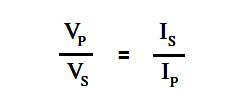
Transformer Current Ratio

where

IP = primary coil current

IS = secondary coil current

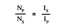
Since the voltage ratio is equal to the turns ratio, we can express the current ratio in terms of the turns ratio, as in below Equation.

Transformer Current Ratio Equation

Example 1:

When operated at 120 V in the primary of an iron core transformer, the current in the primary is 4 amps. Find the current in the secondary if the voltage is stepped up to 500 V.

Solution:

Transformer Current Ratio

Next, we solve for Is

Is = (Vp/Vs) Ip

Is = (120/500) 4

Is = 0.96 amps

Example 2:

A transformer with 480 turns on the primary and 60 turns on the secondary draws Solution: 0.6 amps from a 120 V line. Find Is.

Solution :

Transformer Current Ratio Equation

Next, we solve for Is

Is = (Np/Ns) Ip

Is = (480/60) 0.6

Is = 4.8 amps

We should note from the previous examples that a transformer that “steps-up” voltage, “steps-down” the current proportionally.

Don't Miss Our Updates
Be the first to get exclusive content straight to your email.
We promise not to spam you. You can unsubscribe at any time.
Invalid email address
You've successfully subscribed !

Continue Reading

Types of Capacitors
Series and Parallel Inductors
Series-Wound Motor
DC Generator
Series – Parallel Circuit Analysis
Induction Motor
Share This Article
Facebook Whatsapp Whatsapp LinkedIn Copy Link
Share
Leave a Comment

Leave a Reply Cancel reply

Your email address will not be published. Required fields are marked *

Stay Connected

128.3kFollowersLike
69.1kFollowersFollow
210kSubscribersSubscribe
38kFollowersFollow

Categories

Explore More

Series Open Circuit Faults
Induction Motor Torque Versus Slip
Half-Wave Rectifier Circuit
Transformer Losses and Efficiency
Batteries
Three Phase Systems
AC Generator Nameplate Ratings
Applying Kirchhoff’s Current Law

Keep Learning

Auto Transformer Schematic

Classification of Transformers

3 Phase Balanced Loads

Power in Balanced 3 Phase Loads

LVR Motor Controller Operation

Low Voltage Protection (LVP) and Low Voltage Release (LVR)

Developing a Sine-Wave Voltage of Motor

AC Generation

Induced EMF

Magnetic Circuits

Transformer Efficiency

Transformer Efficiency

Ammeter with Shunt

Ammeter

Three Phase Transformer Connections

Three Phase Transformer Connections

Learn More

Cable Float Level Switch Principle

Cable Float Level Switch Working Principle

Pump Mechanical Seal and thrust bearing Problem

Pump 3-monthly Seal Leaks threaten entire Plant Shut down Indefinitely

Laser Level Measurement

Laser Level Measurement Principle

Introduction to Mechatronics

Introduction to Mechatronics

Classification of Transmission Lines

Classification of Transmission Lines

Closed Tank Level Measurement using DP Transmitter

Cat and Mouse type Level Indicator

Automation in Logistics Industry

Automation in Logistics Industry

How to use Scale and Normalize Instructions in PLC

Scale and Normalize Instructions in PLC

Menu

  • About
  • Privacy Policy
  • Copyright

Quick Links

  • Learn PLC
  • Helping Hand
  • Part Time Job

YouTube Subscribe

Follow US
All rights reserved. Reproduction in whole or in part without written permission is prohibited.
Welcome Back!

Sign in to your account

Username or Email Address
Password

Lost your password?