TDR & FMCW Radar Level Transmitters Principle
Continuous level measurement via radar is based on the theory of the propagation of electromagnetic waves, put forth by the British physicist James C. Maxwell in 1865. Maxwell postulated that the field lines of a changing magnetic field are surrounded by annular electrical field lines, even in the absence of electrical conductors.
Inspired by this theory, German physicist Christian Hülsmeyer immediately applied for a patent for his telemobiloscope, the first radar device of this type in Düsseldorf in 1904. For this innovation, he is rightly known as the the inventor of the „original radar.“
Frequency Modulated Continuous Wave (FMCW) :
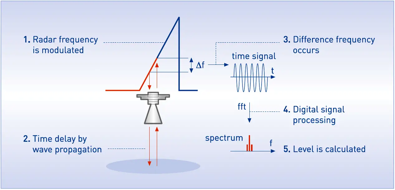
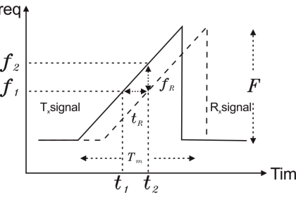
A radar signal is emitted via an antenna, reflected on the product surface and received after a time t. The radar principle used is FMCW (Frequency Modulated Continuous Wave). The FMCW radar emits a high frequency signal whose frequency increases linearly during the measurement phase (called the frequency sweep). The signal is emitted, reflected from the measuring surface and received with a time delay, t. Delay time, t=2d/c, where d is the distance to the product surface and c is the speed of light in the gas above the product. For further signal processing the difference Δf is calculated from the actual transmit frequency and the receive frequency. The difference is directly proportional to the distance.
A large frequency difference corresponds to a large distance and vice versa. The frequency difference Δf is transformed via a Fourier transformation (FFT) into a frequency spectrum and then the distance is calculated from the spectrum. The level results from the difference between tank height and measuring distance.
TDR: Time Domain Reflectometry
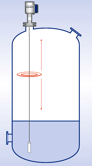
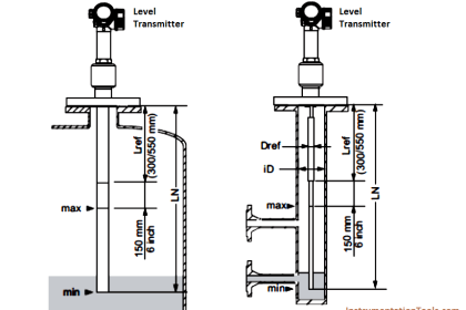
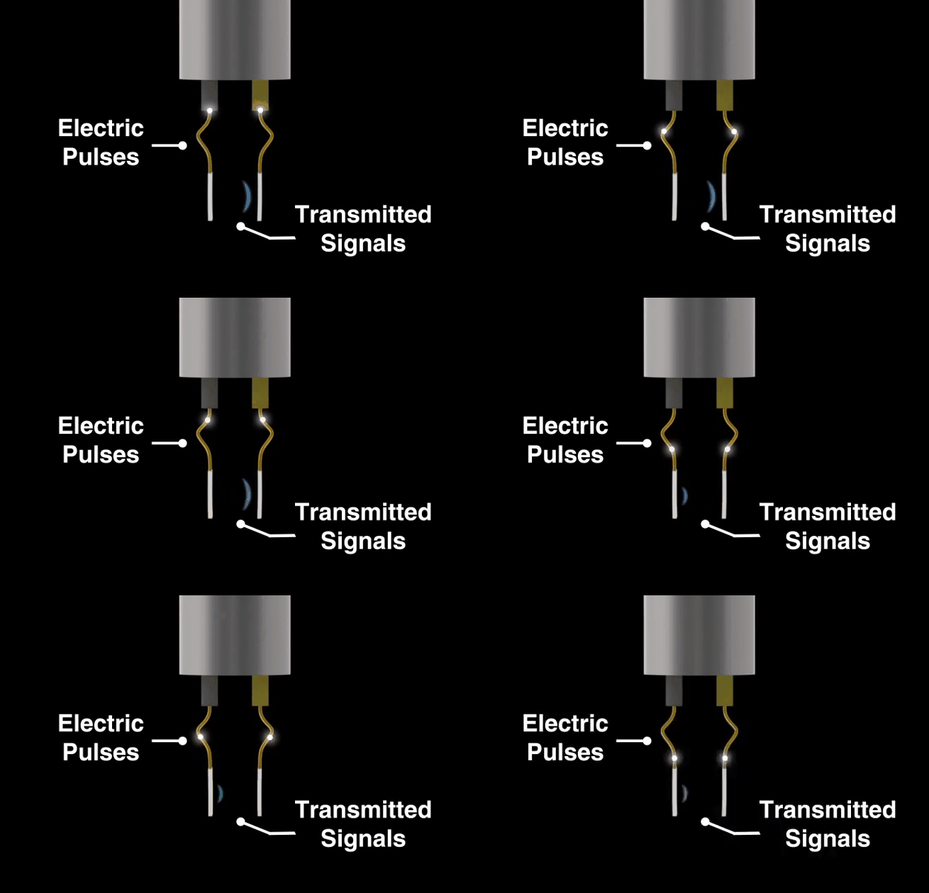
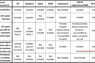
The device transmits low-intensity electromagnetic pulses of approximately one nanosecond width along a rigid or flexible conductor. These pulses move at the speed of light. When the pulses reach the surface of the product to be measured, the pulses are reflected with an intensity that depends on the dielectric constant, εr, of the product (for example, water has a high dielectric constant and reflects the pulse back to the meter converter at 80 % of its original intensity).
The device measures the time from when the pulse is transmitted to when it is received: half of this time is equivalent to the distance from the reference point of the device (the flange facing) to the surface of the product. The time value is converted into an output current of 4 to 20 mA and/or a digital signal.
Dust, foam, vapor, agitated surfaces, boiling surfaces, changes in pressure, temperature and density do not have an effect on device performance.
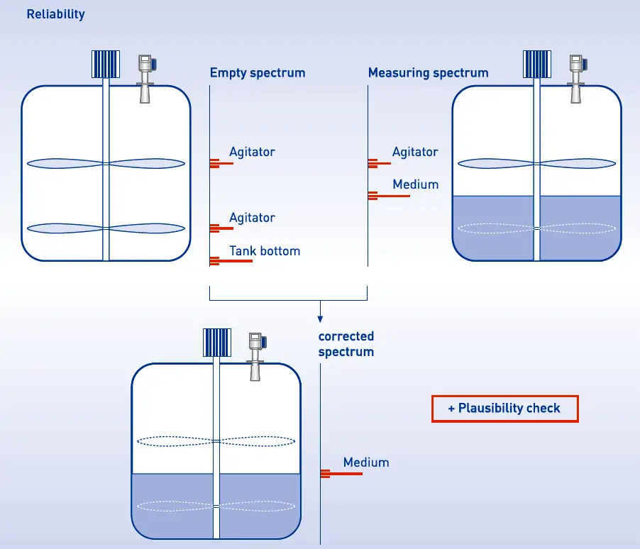
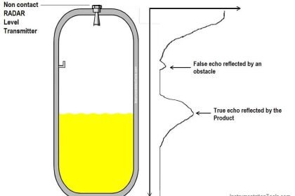
Empty spectrum
All interference reflections, which are caused by fixed or moving tank inserts and the bottom of the tank, can be detected and saved by recording an empty spectrum. The surface reflections are reliably detected, distinguished from interference reflections and analyzed by comparing the empty spectrum to the reflections in the filled state. For applications with tanks that cannot be emptied at the time of the start-up, the radar meters offer the capability of recording a partially empty spectrum.
Source : Khrone
Image Credits : Khrone
