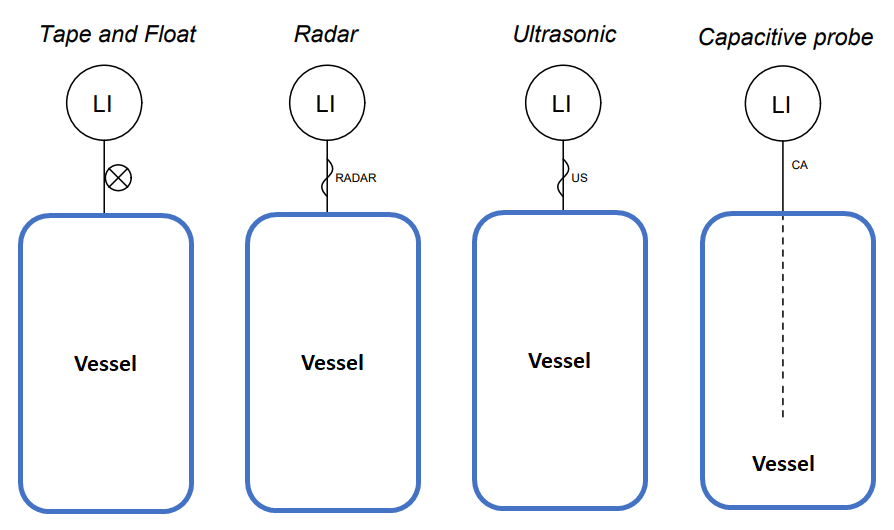
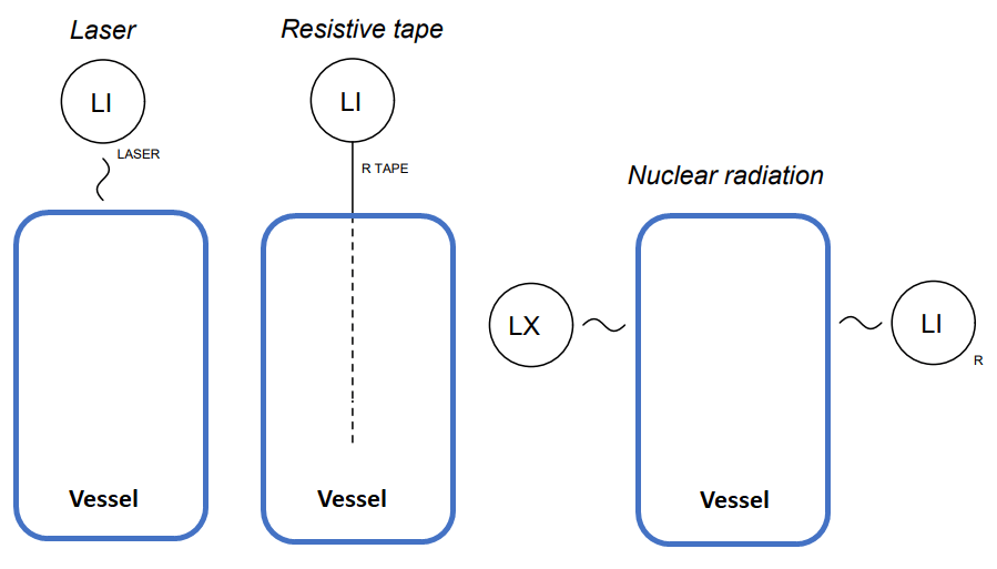
Draw the symbols for the following types of liquid level indicating instruments, each one mounted to the top of a process vessel:
- Tape and float
- Radar gauge
- Ultrasonic (sound) gauge
- Laser (light) gauge
- Capacitive probe
- Nuclear radiation
- Resistive tape
Level Sensor Symbols