Inst ToolsInst ToolsInst Tools
  • Courses
  • Automation
    • PLC
    • Control System
    • Safety System
    • Communication
    • Fire & Gas System
  • Instrumentation
    • Design
    • Pressure
    • Temperature
    • Flow
    • Level
    • Vibration
    • Analyzer
    • Control Valve
    • Switch
    • Calibration
    • Erection & Commissioning
  • Interview
    • Instrumentation
    • Electrical
    • Electronics
    • Practical
  • Q&A
    • Instrumentation
    • Control System
    • Electrical
    • Electronics
    • Analog Electronics
    • Digital Electronics
    • Power Electronics
    • Microprocessor
Search
  • Books
  • Software
  • Projects
  • Process
  • Tools
  • Basics
  • Formula
  • Power Plant
  • Root Cause Analysis
  • Electrical Basics
  • Animation
  • Standards
  • 4-20 mA Course
  • Siemens PLC Course
Reading: Structured Text PLC Programming for Two-Tanks Level Application
Share
Notification Show More
Font ResizerAa
Inst ToolsInst Tools
Font ResizerAa
  • Courses
  • Design
  • PLC
  • Interview
  • Control System
Search
  • Courses
  • Automation
    • PLC
    • Control System
    • Safety System
    • Communication
    • Fire & Gas System
  • Instrumentation
    • Design
    • Pressure
    • Temperature
    • Flow
    • Level
    • Vibration
    • Analyzer
    • Control Valve
    • Switch
    • Calibration
    • Erection & Commissioning
  • Interview
    • Instrumentation
    • Electrical
    • Electronics
    • Practical
  • Q&A
    • Instrumentation
    • Control System
    • Electrical
    • Electronics
    • Analog Electronics
    • Digital Electronics
    • Power Electronics
    • Microprocessor
Follow US
All rights reserved. Reproduction in whole or in part without written permission is prohibited.
Inst Tools > Blog > PLC Tutorials > Structured Text PLC Programming for Two-Tanks Level Application

Structured Text PLC Programming for Two-Tanks Level Application

Learn how to write a structured text PLC programming for the two-tanks level control application for beginners.

Last updated: September 13, 2024 2:16 pm
Viral Nagda
PLC Tutorials
1 Comment
Share
4 Min Read
SHARE

When you are using structured text for PLC programming, it helps a lot in saving time and decoding the logic easily. It requires a good knowledge of syntax and instruction format. Once written, you can write the complex logics easily.

Contents
Structured Text for two-tank level applicationStructured Text PLC Programming

One system which is used widely in many processes is controlling the level of two tanks. Because tanks are used in many applications, it must be understood to write the logic properly. In this post, we will see how to write a PLC program for controlling the level of two tanks using structured text.

Structured Text for two-tank level application

Let us understand the case scenario first. Refer to the below image. There are two tanks in the system. Both the tanks have two level switches (/sensors) each – low and high.

Structured Text PLC Programming for Two-Tanks Level Control

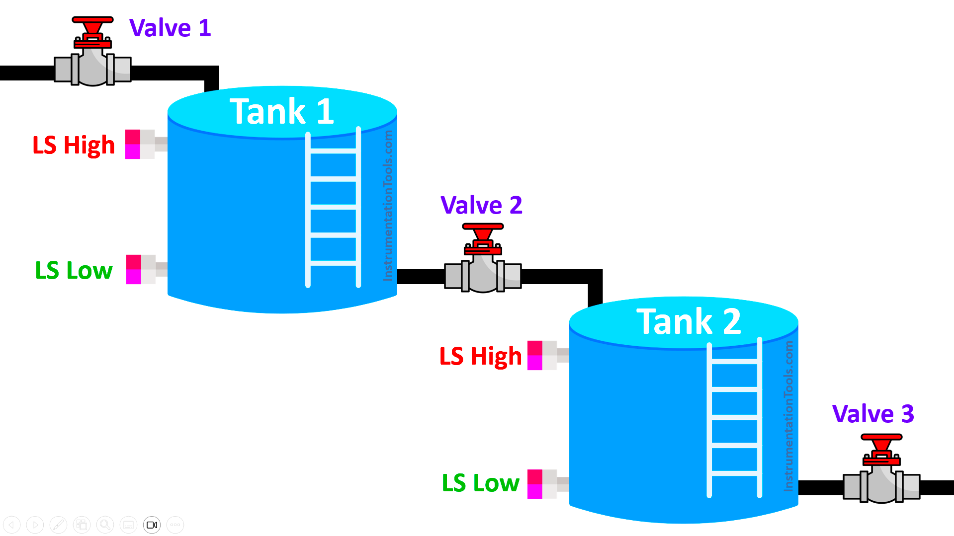
The first tank is filled by a valve. The second tank is drained by a valve. In between the two tanks, another valve which drains the first tank as well as fills the other tank.

When any level is low, then the drain valve will remain closed. When any level is high, then the filling valve will remain closed. The valve remains closed as long as the level is not healthy; once healthy, then it will open again.

Structured Text PLC Programming

Now, let us see the logic to be written. As we are using structured text, we will use simple if-else statements for understanding it.

Refer to the below image. There are four PLC inputs – tank-1 level high, tank-1 level low, tank-2 level high, and tank-2 level low.

There are three PLC outputs – valve-1, valve-2 and valve-3.

ST Example PLC Program Tank Level

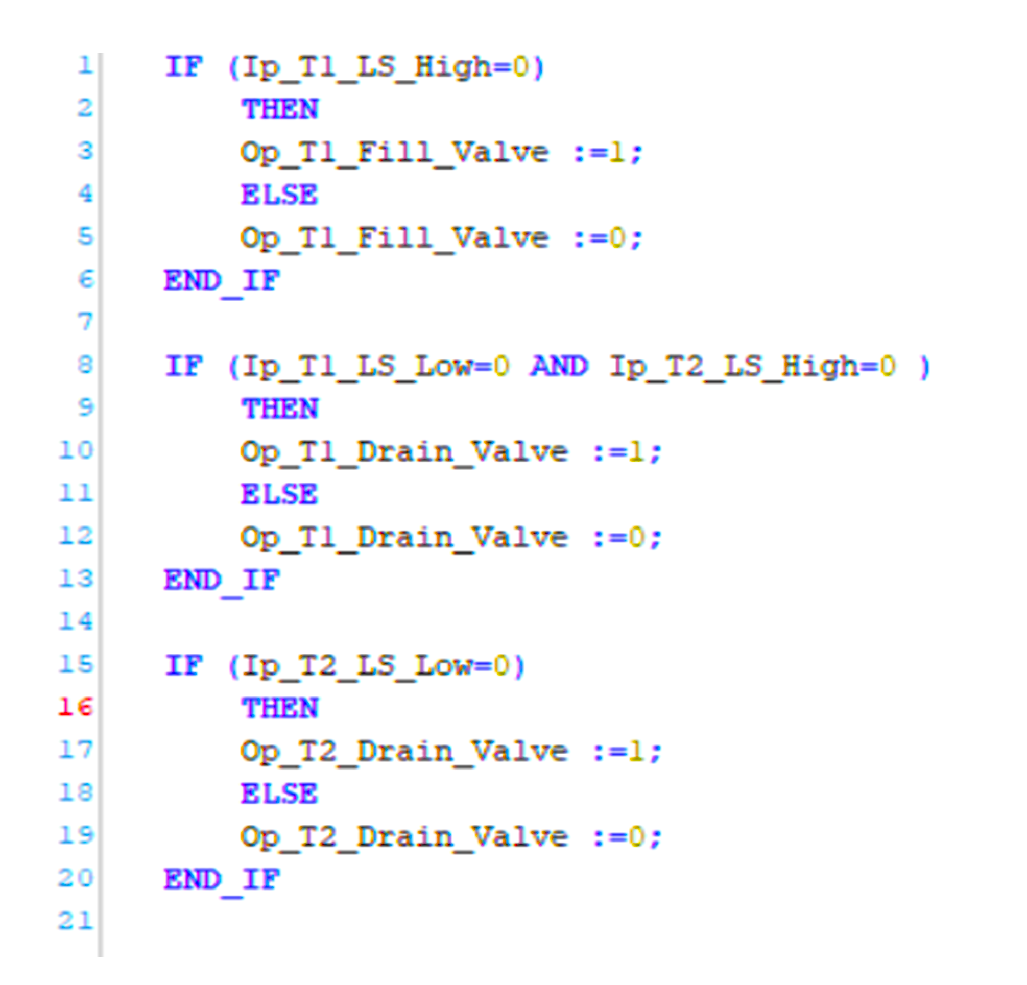
First, we will see how to fill tank-1. If the level of tank-1 is high, then the valve will remain off. So, we used an if-else statement where, if the value of the sensor is zero, it means the level is normal and the valve output will be written as 1. Else, it will be written as 0.

Now, we will see how to fill tank-2 and drain tank-1. If the level of tank-2 is high or the level of tank-1 is low, then the valve will remain off. So, we used an if-else statement where, if the value of both the sensors are zero, it means the level is normal and the valve output will be written as 1. Else, it will be written as 0.

Now, we will see how to drain tank-2. If the level of tank-2 is low, then the valve will remain off. So, we used an if-else statement where, if the value of the sensor is zero, it means the level is normal and the valve output will be written as 1. Else, it will be written as 0.

Due to this logic, the valves control the level of the tanks and avoid them from being overfilled or the drain valves remaining open unnecessarily in case of empty-tank. The valves work in tandem with each other and thus control the levels of both the tanks.

In this way, we saw how to write a PLC program for controlling the level of two tanks using structured text language.

Read Next:

  • Inside the PLC Control Panel: Test Quiz
  • Which Language is Best for PLC Programming?
  • Exhaust Fan Control: Example of PLC Timer Logic
  • PLC Program to Drain Products from Two Tanks
  • Automation Solutions Logic for Stairway Lighting
Don't Miss Our Updates
Be the first to get exclusive content straight to your email.
We promise not to spam you. You can unsubscribe at any time.
Invalid email address
You've successfully subscribed !

Continue Reading

PLC Logic GATE Program
How to Design a System Architecture in Industrial Automation?
Sorting & Distribution Line PLC Programming – Advanced Logic
PLC Functional Block Diagram for Logic Gates
What is Sequential Function Chart (SFC?)
What is Midline Instruction in Siemens PLC?
Share This Article
Facebook Whatsapp Whatsapp LinkedIn Copy Link
Share
1 Comment
  • Romelroy4702 says:
    September 30, 2024 at 12:02 pm

    The Process explanation has to be like this as follows:- Initial Condition: LLST1 & LLS T2 should be ON. When Push button Start (Pb Start) is pressed ON, Motor ON.

    When HLST1 becomes ON, Motor becomes OFF & V1 gets ON. Then so on. If you need the details of this whole Process kindly, message in this. Thank you

    Reply

Leave a Reply Cancel reply

Your email address will not be published. Required fields are marked *

Stay Connected

128.3kFollowersLike
69.1kFollowersFollow
208kSubscribersSubscribe
38kFollowersFollow

Categories

Explore More

Advanced PLC Programming for Defective Parts Sorting
PLC Sequential Operation Example Program
PLC Hoist Crane Programming: Example using Schneider
Global Acknowledgment Instruction in Safety PLC
PLC Tag Naming Conventions
FB Block in Siemens PLC Programming
Hardwired I/O and Serial I/O – Differences Explained
Draw a Ladder Logic to switch ON-OFF a Bulb using a Toggle Switch ?

Keep Learning

SCADA System

What is SCADA System?

Allen Bradley SLC 500 PLC Programming

PLC Commissioning and Testing

PLC Commissioning and Testing Procedure (Programmable Logic Controller)

PLC Program for Daily Production Record

PLC Program for Daily Production Record

Introduction to PLC

#9 PLC Best Practices – Validate indirections

HART Transmitters Loop Checks

Loop Check of 4-20mA or HART Transmitters

PLC based Auto Manual Operation of Roll down Shutters

PLC based Auto/Manual Operation of Roll down Shutters in Industry

Run 4 Motors Sequentially from Same Push button PLC Program

Run 4 Motors Sequentially from Same Push button PLC Program

Learn More

Top 100 PLC Projects List

Top 100 PLC Projects List

ultrasonic-level-measurement

Ultrasonic Level Transmitter Working Principle

Asynchronous Motor Animation

Asynchronous Motor Animation

Hall Effect Transducers Objective Questions

Hall Effect Transducers Objective Questions

Digital Electronics Multiple Choice Questions

Programmable Array Logic Objective Questions

Optimal Control Systems

Parameter Optimization : Servomechanims

Frequency Response MCQ

All-pass & Minimum-phase Systems

PLC based Drink Dispenser System

PLC based Drink Dispenser System

Follow US
All rights reserved. Reproduction in whole or in part without written permission is prohibited.
Welcome Back!

Sign in to your account

Username or Email Address
Password

Lost your password?