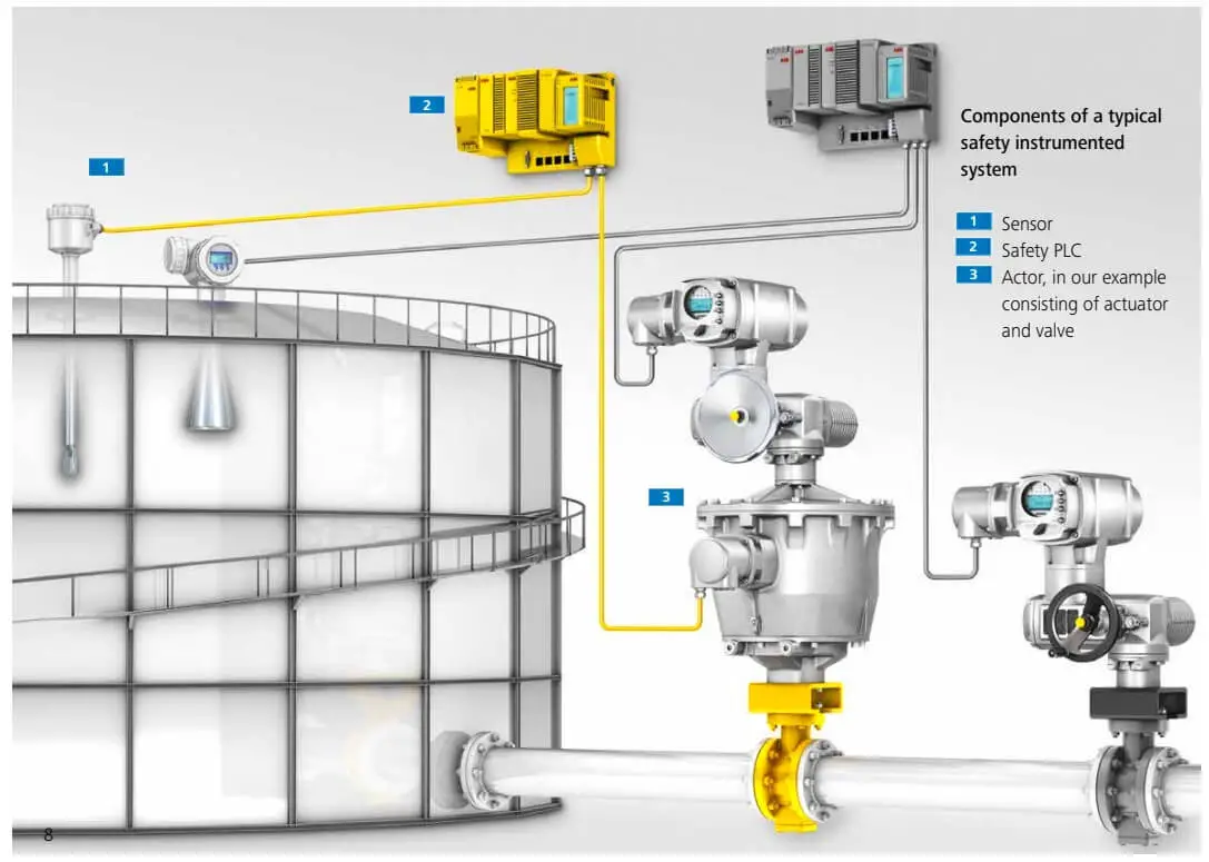
In Safety Instrumented System (SIS), Hardware fault tolerance is very vital to ascertain how long SIS can perform with the designed integrity.
Fault Tolerance is the ability of a functional unit to continue to perform a required function in the presence of faults or errors.
Fault Tolerance is one of the requirements that the Automation/Safety Design must meet to achieve the required safety.
In general, three forms of proof are required to claim that an SIS reaches a particular safety integrity level.
Hardware fault tolerance provides protection against Random failures. If it would result in additional failures and lead to decreased overall process safety, then the HFT may be reduced. This shall be justified and documented.
The justification shall provide evidence that the proposed architecture is suitable for its intended purpose and meets the safety integrity requirements.
The HFT requirements in below table represent the minimum system or, where relevant, the SIS subsystem redundancy.
Depending on the application, device failure rate, and proof-testing interval, additional redundancy can be required to satisfy the failure measure for the SIL of the SIF.
| SIL Level | Minimum required HFT |
| SIL 1 (Low/High/Continuous demand mode) | 0 |
| SIL 2 (Low demand mode) | 0 |
| SIL 2 (High/Continuous demand mode) | 1 |
| SIL 3 (Low/High/Continuous demand mode) | 1 |
| SIL 4 (Low/High/Continuous demand mode) | 2 |
As per IEC: 61511 “For all subsystems (for example, sensor, final elements, and non-PE logic solvers) excluding PE logic solvers the minimum fault tolerance specified in the above table may be reduced by one”.
In other words, SIL-2 SIS’s (Low demand) do not need any fault tolerance if:
One may decrease the minimum fault tolerance requirement by 1 if ALL the following apply:
Alternately one must Increase the minimum hardware fault tolerance by 1 if:
The dominant failure mode is in the dangerous state & At least 60% of dangerous failures are not detected.
Fault tolerance is the preferred solution to achieve the required confidence that a robust architecture has been achieved.
When these conditions are satisfied, the purpose of the conclusion is to demonstrate that the proposed alternative architecture provides an equivalent or better solution.
This may vary depending on the application and/or the technology in use
A few examples are Backup arrangements (e.g., Analytical redundancy, replacing a failed sensor output with physical calculation results from other sensors outputs)
Using more reliable items of the same technology (as applicable)
Changing for a more reliable technology
Decreasing common cause failure impact by using diversified technology
Increasing the design margins (where it’s allowed)
Constraining the environmental conditions (e.g. for electronic components)
Decreasing the reliability uncertainty by gathering more field feedback or specialist opinion.
If you liked this article, then please subscribe to our YouTube Channel for Electrical, Electronics, Instrumentation, PLC, and SCADA video tutorials.
You can also follow us on Facebook and Twitter to receive daily updates.
Read Next:
PLC ladder logic design to control 3 motors with toggle switch and explain the program…
VFD simulator download: Master the online tool from the Yaskawa V1000 & programming software for…
The conveyor sorting machine is widely used in the packing industries using the PLC program…
Learn the example of flip-flop PLC program for lamps application using the ladder logic to…
In this article, you will learn the STAR DELTA programming using PLC controller to start…
Lube oil consoles of rotary equipment packages in industrial process plants are usually equipped with…
