Whenever you are simulating a PLC program in industrial automation, it helps a lot before going to the site for commissioning. It saves time, reduces bugs during commissioning and also readies the programmer for any uncertain activity.
In almost all the automation softwares, an option is available for simulation. One of the most used brands in industrial automation is Rockwell Automation. Here too, you can simulate PLC and HMI softwares.
In this post, we will see how to do a simulation between Studio 5000 and FactoryTalk View Studio.
Required Softwares
Softwares Required for Simulation of Studio 5000 and FactoryTalk View Studio:
First of all, let us see what are the softwares required initially for simulation.
- Studio 5000 (for PLC)
- FactoryTalk View Studio (for HMI)
- RSLogix Emulate (for simulation)
- RSLinx Classic (for communication path)
Studio 5000 and FactoryTalk View Studio
The steps for the Simulation of Studio 5000 and FactoryTalk View Studio are mentioned below.
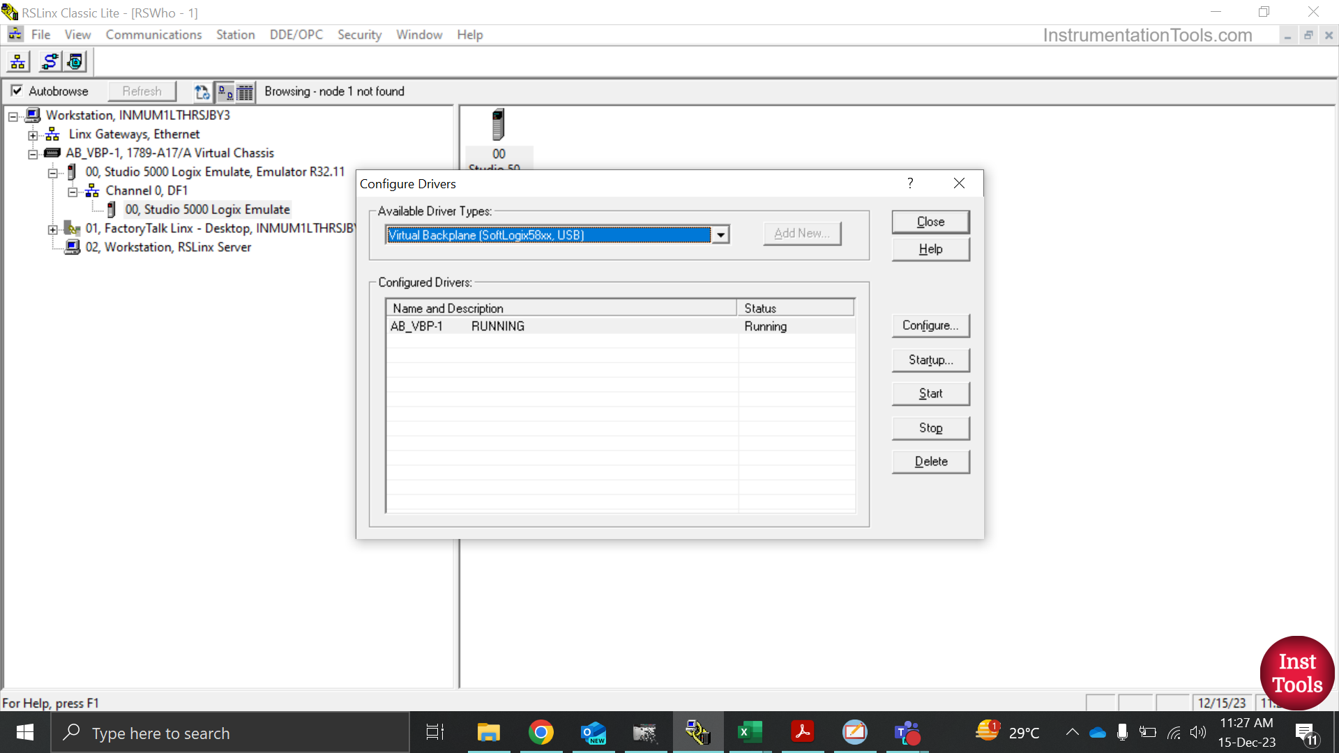
First, let us start with RSLinx Classic. This software is required for establishing a communication path between PLC and HMI softwares. You can configure various types of drivers here like Ethernet, DH485, Emulation, etc. for determining how communication will be established between automation devices and your laptop.
In our case, we will use the driver of the Emulator. Here, we will add a driver first, namely – Virtual Backplane (SoftLogix 58xx, USB).
You will be asked to put a name for the driver. Name it accordingly. Here, we have named it AB_VBP-1. Then, it will ask for a slot number. The slot number is where your CPU is located. In our case, we will use the number 0.
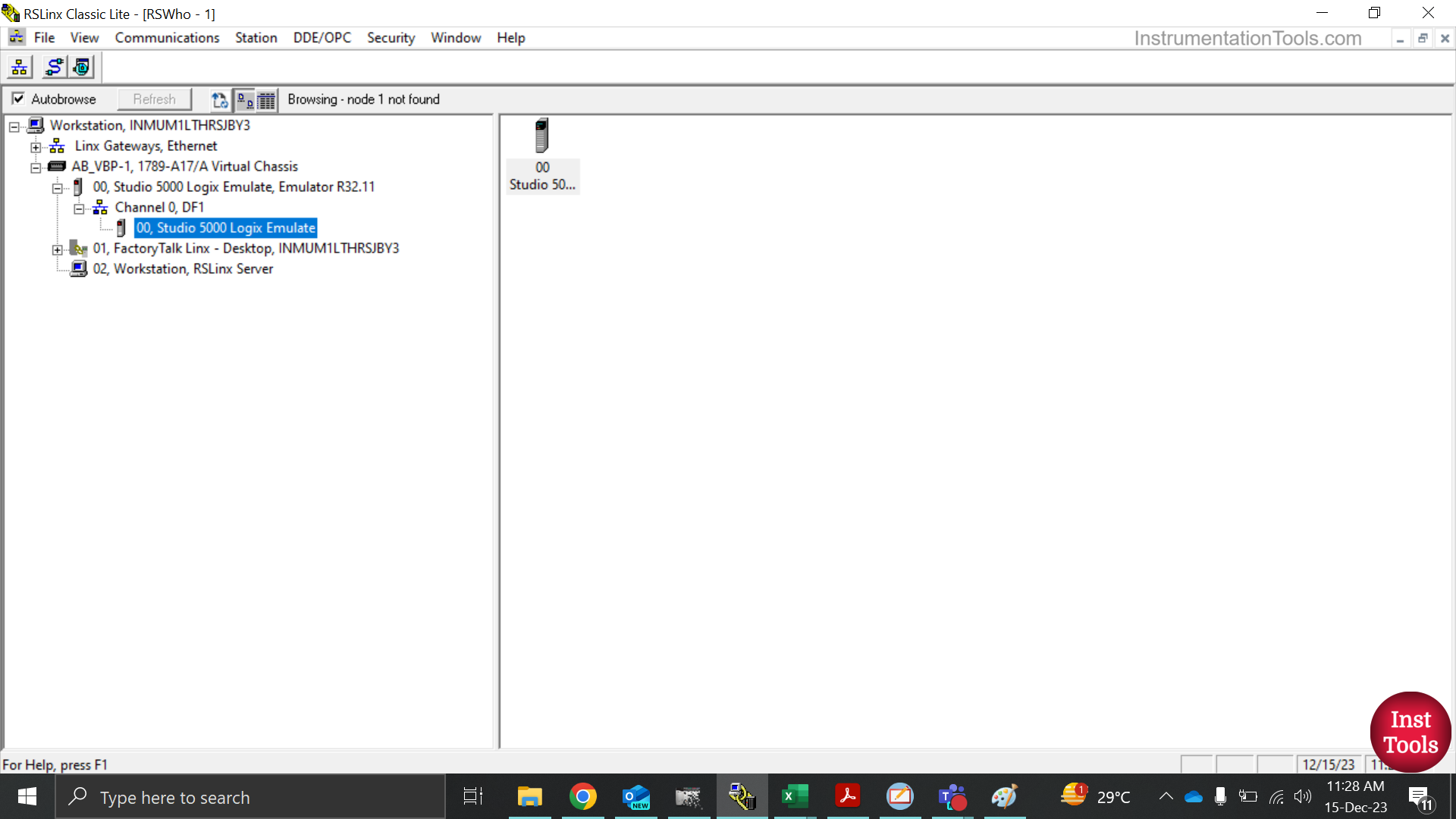
Once you add it, you will see a path created as shown below. Click the emulate option as shown.
Now, you have properly assigned an emulator communication path in the software.
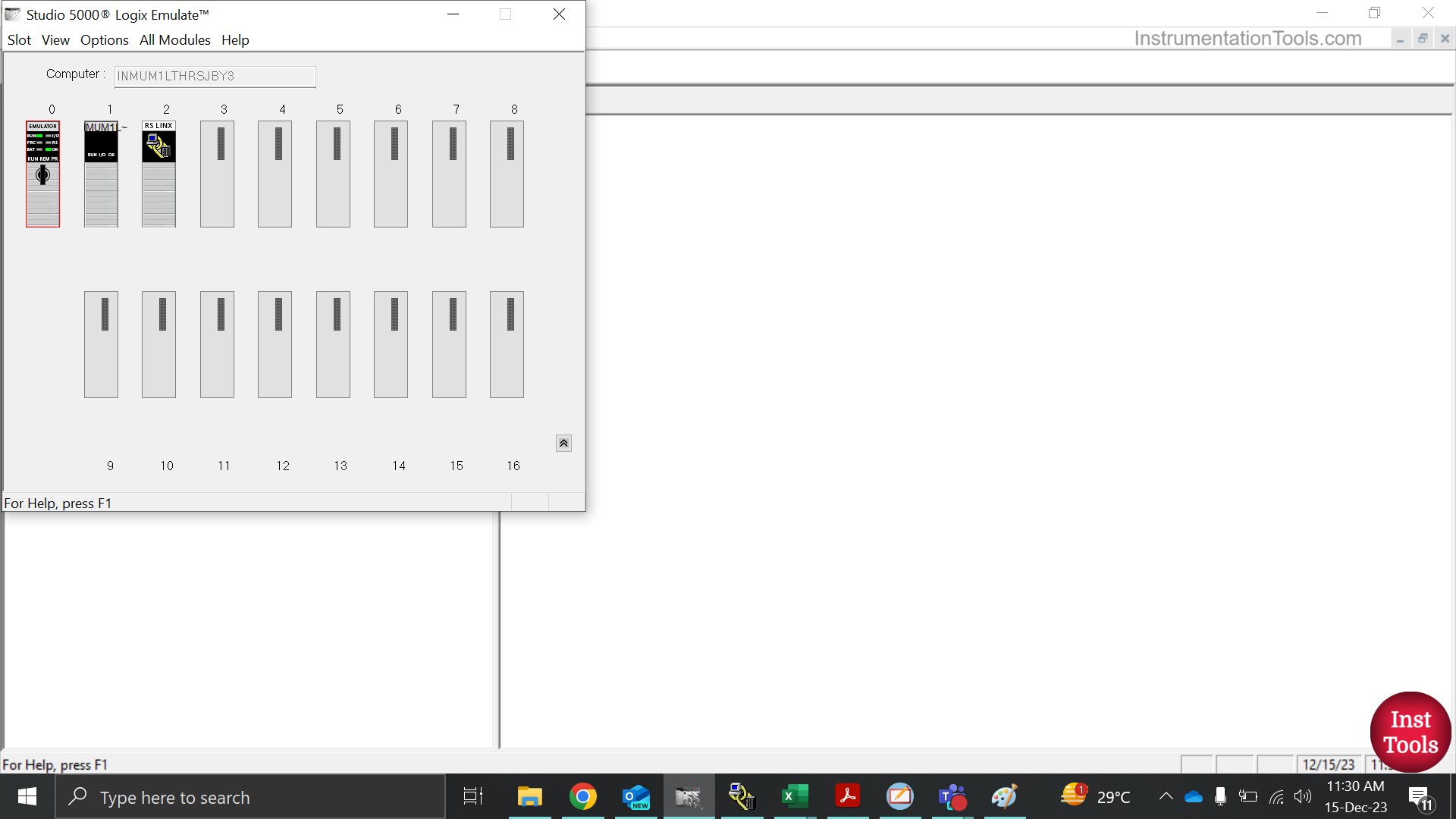
Now, open RSLogix Emulate. This software is used for assigning the PLC in the simulation path. Here, we had earlier given slot 0 for emulation.
So, we will create an emulator PLC in slot 0 as shown below by right-clicking slot-0 and selecting the create option. Then, we will select the emulate 5570 controller.
Next, there is no need to change any settings. Directly click the next button. Then, click the finish button.
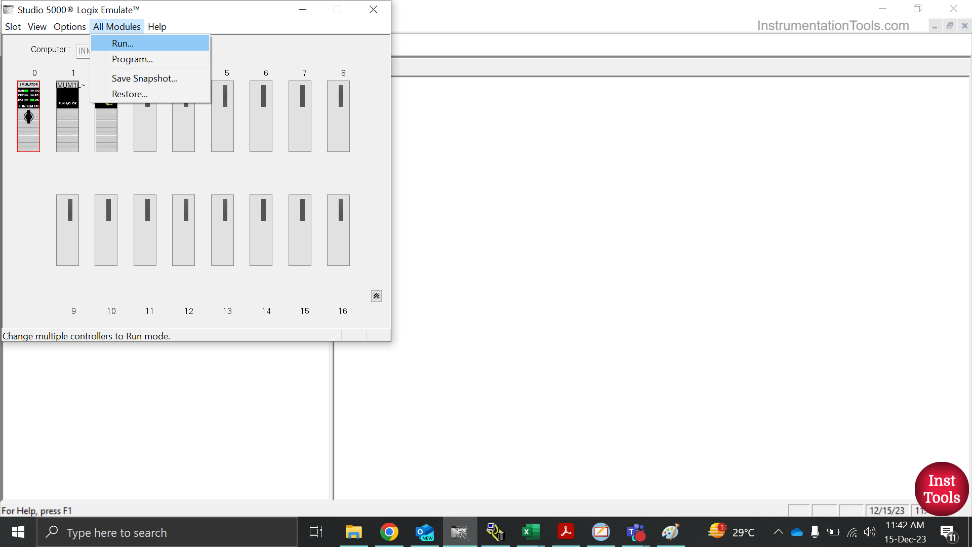
Now, click the run option in the all modules section of the toolbar in the software as shown in the second image. This will put slot-0 in run mode and your emulator is now running properly.
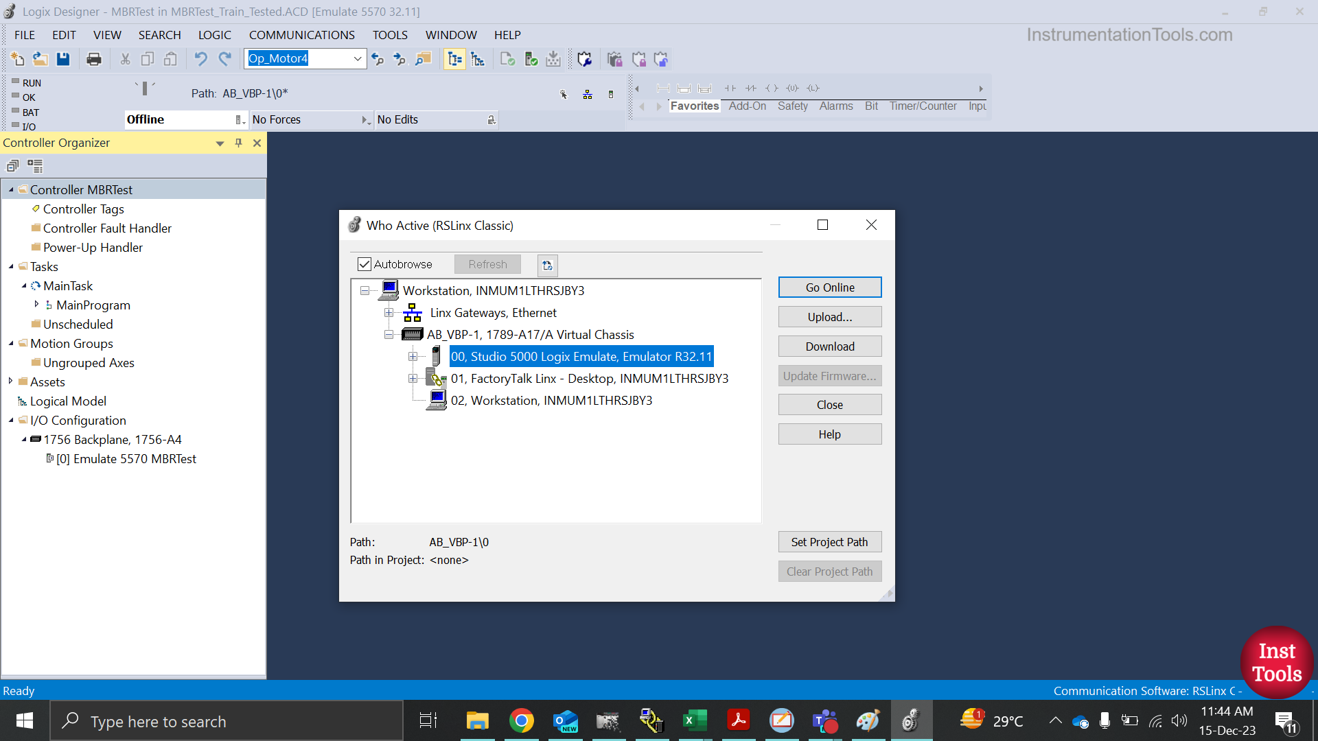
Next, you have to download the PLC program in the emulator and put PLC in run mode. Refer to the below image. You have to select the Who Active option in the communications option of the PLC software toolbar.
Here, you will be shown many communication paths active in the RSLinx software. In the image, you have to choose RS Emulate in the slot-0 path that you have defined.
Click it and select the download option. This will download the program and then, you have to put the PLC in run mode.
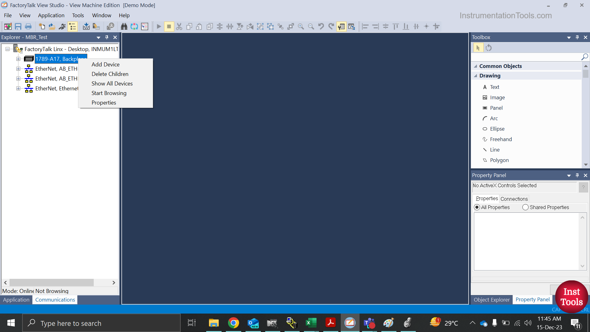
Now, you have to configure FactoryTalk software for establishing communication for HMI runtime. Refer to the below image. There are two options in the left-hand toolbar of the software – application and communications.
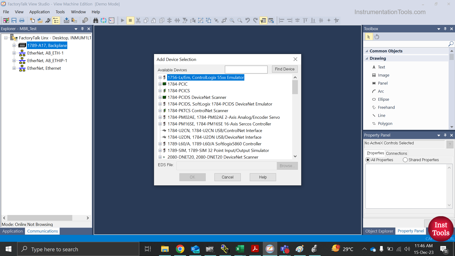
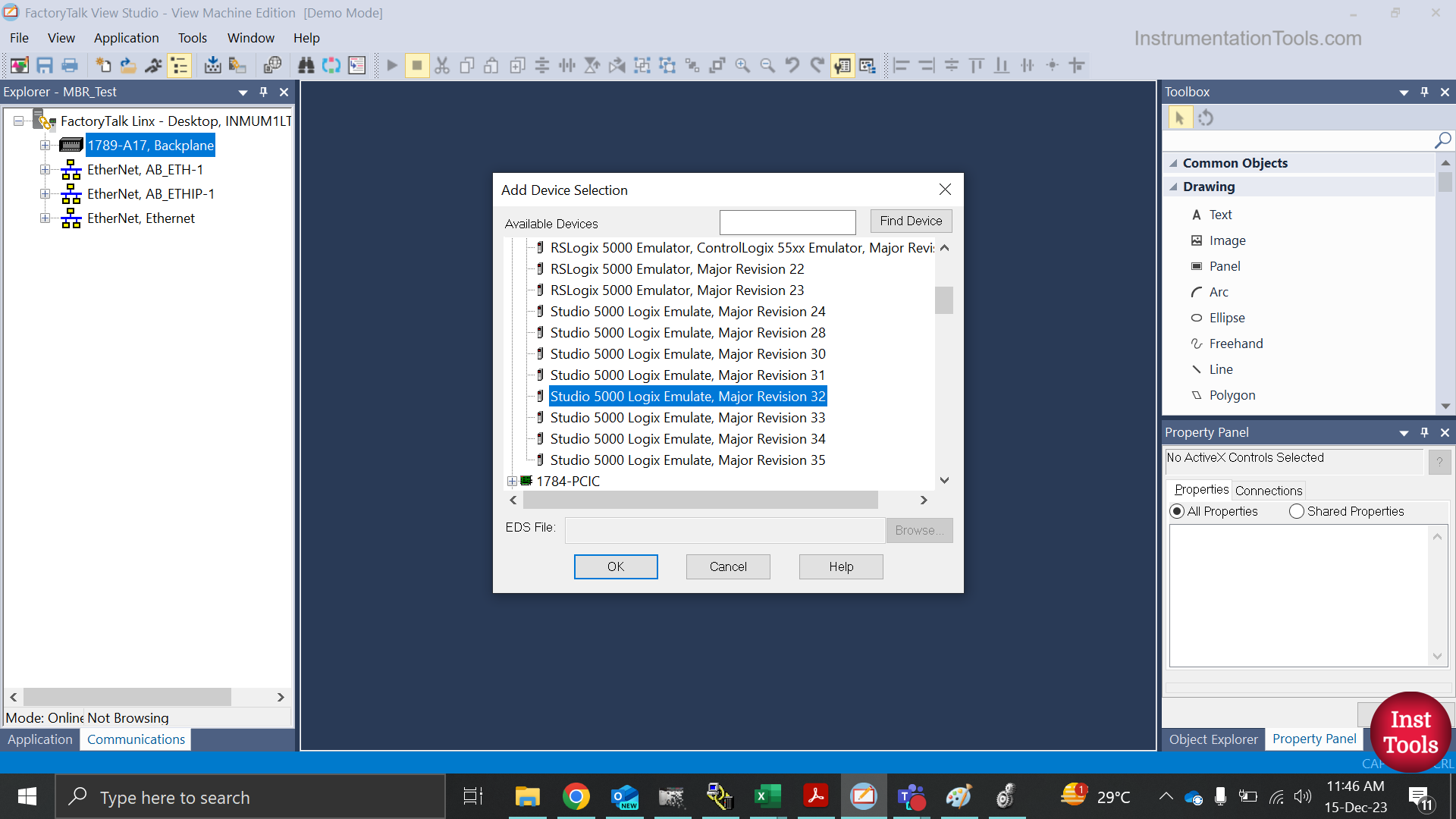
In the communications tab, you have to right-click 1789-A17 Backplane option and add a new device. The device that you will add here is Emulator as shown in the second and third image.
Now, refer to the below image. First, you have to double-click the communication setup in FactoryTalk Linx as shown in A part. Here, you have to define a shortcut which will be the reference for communication between PLC tags and HMI tags as shown in B part.
Basically, when you assign tags in HMI objects, this shortcut name will come first before the actual PLC tag. This will show that the PLC tag is the same that you have used in your PLC project for communication.
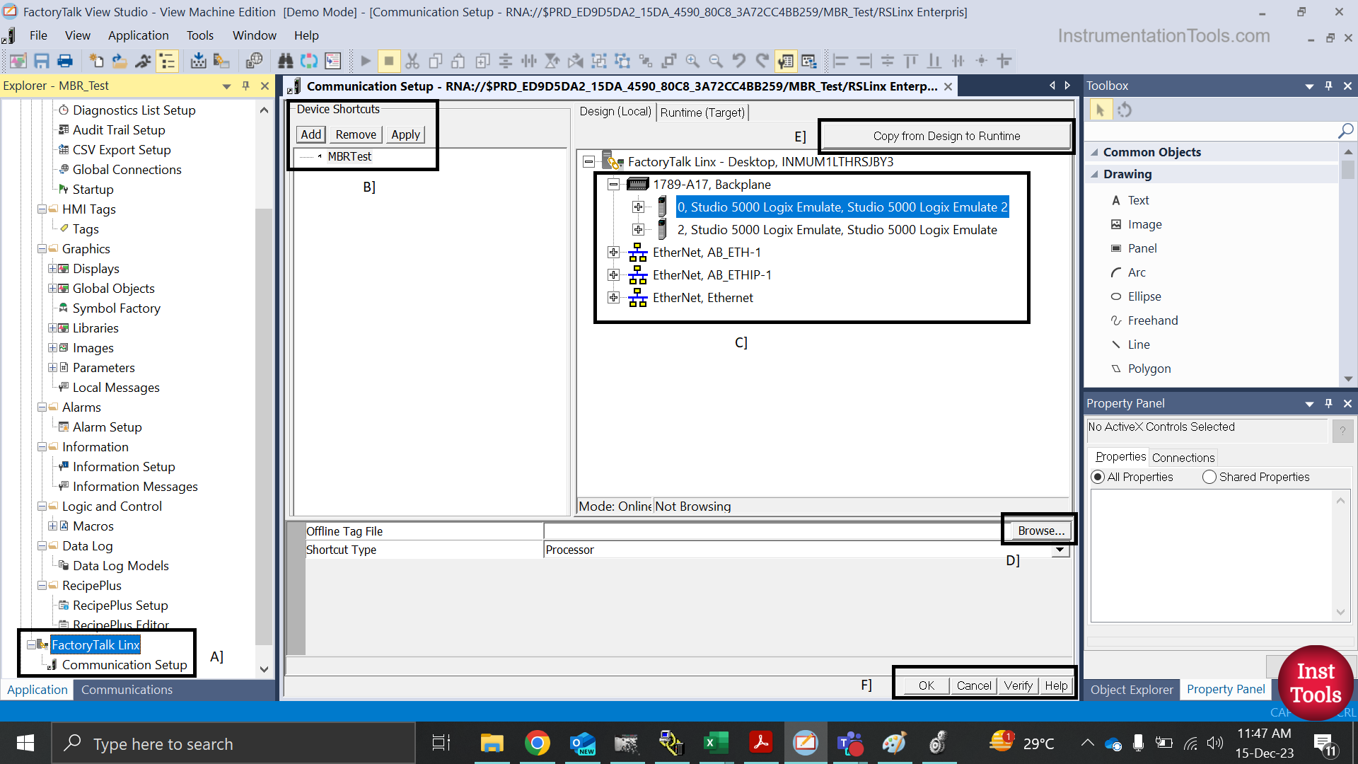
Then, you have to choose the communication path as shown in the C part. These paths are directly linked with RSLinx and will automatically show you the active paths.
Choose the correct name that you have created earlier. Then, browse for your PLC project name in the D part as shown. Then, click the apply button in B part. This action will assign your PLC shortcut and PLC project to the communication part.
Then, click copy from design to runtime button in E part. In the last step, click the verify button in part F. This will give you an answer of whether your PLC has been assigned with HMI or not.
Once verified, click the Ok button in F part. All your steps are over and you can then run your HMI program on simulation.
If you liked this article, then please subscribe to our YouTube Channel for Instrumentation, Electrical, PLC, and SCADA video tutorials.
You can also follow us on Facebook and Twitter to receive daily updates.
Read Next:
- PLC-to-PLC Communication Project
- IO Signals Sharing Between PLC Systems
- Calling a Function Block in a PLC System
- Siemens Communication with I-Device
- PLC Programming Projects for Beginners