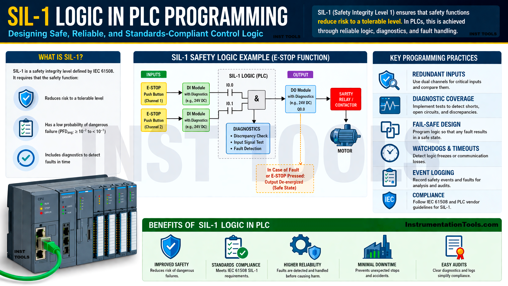
SIL (safety integrity level) is the most required and reliable available programming for very critical industries where safety is a must. It has various levels defined in instrumentation. So, the programmers need to identify the difference between all the levels so that they can write the logic accordingly for their corresponding automation systems. This helps to keep a clear buffer between the systems according to their safety requirements and helps to increase efficiency and reliability. Starting with this post, we will first see the SIL-1 logic and understand how it is implemented.
What is SIL logic in instrumentation?
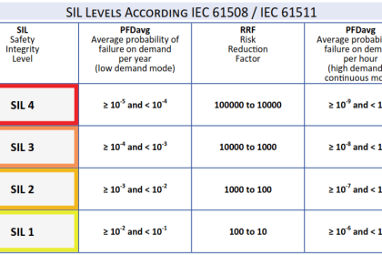
For starters, let us first understand what SIL logic is in instrumentation. As the name implies, it is a standard through which all safety levels are tried to be maintained in a system, based on the level selected. The levels are from 1 to 4. In short, you have an automation system where it is required that it should not fail at all, otherwise the safety of the personnel and environment is compromised.
SIL is thus used in widely known critical systems and functions like emergency shutdown, gas detection, level shutdown, fire detection, high temperature shutdown, pressure trip, etc. So, in short, SIL logic tells the system how safe and reliable your safety logic must be, so that the process works efficiently and reliably. The logic, as classified into four levels, means the lowest level has the lowest safety achievement, which increases as the level increases. Let us now see below how to write SIL-1.
What are the basic principles to be followed in SIL-1?
Starting with SIL-1, this is the starting level of the safety instrumentation. Before writing any PLC program for implementing this level, it is always necessary to understand the basics. If you are not clear what the requirements of SIL-1 are, first of all, then you cannot jump to write the topic directly.
So, let us understand what basic principles need to be followed in SIL-1.
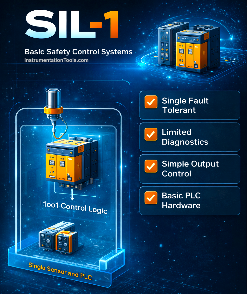
- As you are protecting a system safely, you obviously require some inputs taken from the field as feedback. In this case, even one sensor is enough to achieve safety at this level. So, it is good enough for normal industrial risks.
- Diagnostics is required for the instruments at a very basic level, like instrument healthiness, whether it is in the valid scaled range, and wire break.
- No voting logic is required in SIL-1 ( voting involves multiple sensors, which is not valid here).
- An alarm must never be auto-reset and should be compulsorily manually reset. This ensures that no unwanted on and off of a system occurs, and the user has personally verified that the fault has been cleared before resetting that alarm.
- Use only small time delays to avoid nuisance alarms. This ensures that the alarms are not generated unnecessarily and avoids unwanted logging of data in the system.
- The PLC IO modules must support broken wire configuration, short circuit enable option, out of range diagnostics, and isolation between channels. Output cards must be set to de-energize instead of hold for any module fault or controller fault.
SIL-1 Logic in PLC Programming
- The very first thing to check is that when you read an analog input, it must be within the range. A wire break or short circuit alarm for that input must be given the highest priority and made to trip the logic accordingly. If you do not have any in-built system or diagnostic bit, you can also write the logic manually, by comparing the value between the lowest and highest values.
- If the signal is valid and the process value crosses the set alarm limit, then the trip signal must be generated. But remember to use a check timer, for a digital or analog signal, to avoid nuisance alarms and prevent the system from overflooding with alarms unnecessarily.
- Once an alarm occurs, the alarm must be set till the operator comes, acknowledges, and manually resets the alarm. Also, the reset button must ensure that it is both a soft signal from HMI / SCADA or a hardwired push button. If any of the values come, then the alarm can be reset.
- Then, if such critical alarms occur (be it software, hardware, or controller level), the output must be immediately de-energized to a false state as per the alarm process interlock written in the control philosophy.
- All the fault and diagnostics bits generated must be immediately communicated to HMI / SCADA systems to alert the operators to that. This ensures that they can take timely action and rectify the same.
- The process logic can be written as per your requirement, but care must be taken that the above steps mentioned have the highest priority and bypass the other conditions in the process, to achieve safety integrity.
SIL-1 logic looks similar to normal PLC logic. But the difference is not the complexity; the difference is in the requirements, restrictions, and behaviours that make it “SIL-capable”. SIL-1 is about making normal logic behave in a safe, predictable, auditable, and fail-safe way.
So, strict safety rules are employed in the logic, rather than making them a secondary one like in a normal PLC, where only alarms will be generated, but no action will be taken (again, it depends on the criticality of the process). So, the following rules are compulsory to write and follow in SIL-1 – wire break detection, forcing safe output, short circuit detection, proof test capability, out of range detection, no timers delaying trips as soon as they are detected, but small timers for detecting trips, no auto-reset after trips, and safe-state enforcement.
Normal process logic often tolerates noises, delays, retries, bad values, etc., but SIL-1 logic does not tolerate them. Safety logic must be readable and traceable easily, with no long formulas, nested IFs, indirect addressing/array tricks, or mixing of functions. SIL-1 requires PLC hardware configuration rules, like dedicated safety tasks, hardware reset inputs, shielding and grounding rules, and fail-safe module configuration.