SIL-2 represents the next level of safety instrumentation, building directly on the principles of SIL-1. Before attempting to design or program a SIL-2 safety function, it is essential to have a solid understanding of SIL-1 requirements. SIL-2 does not replace SIL-1 fundamentals; rather, it strengthens and extends them.
Without clarity on SIL-1 concepts such as fail-safe behavior, diagnostics, and manual reset philosophy, it is not possible to correctly implement SIL-2 logic. Therefore, before moving into SIL-2 programming, we must first revisit and understand the core principles established at the SIL-1 level. Refer to our earlier SIL-1 article for more details. In this post, we will see how to write SIL-2 logic in PLC programming.
SIL 2 Logic Design
Continuing the same principles of SIL-1, SIL-2 represents a higher level of safety instrumentation and requires a thorough understanding of its fundamental principles before any PLC programming is attempted.
Implementing SIL-2 logic is not simply about writing code; it involves meeting specific safety requirements such as redundancy, diagnostics, fault tolerance, and fail-safe behavior. Without a clear understanding of these requirements, it is not possible to correctly design or implement SIL-2 safety functions.
Therefore, before moving directly into PLC programming, it is essential to first understand the basic principles that must be followed for SIL-2 systems.
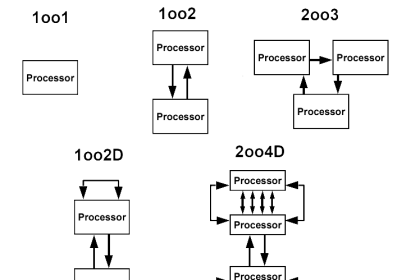
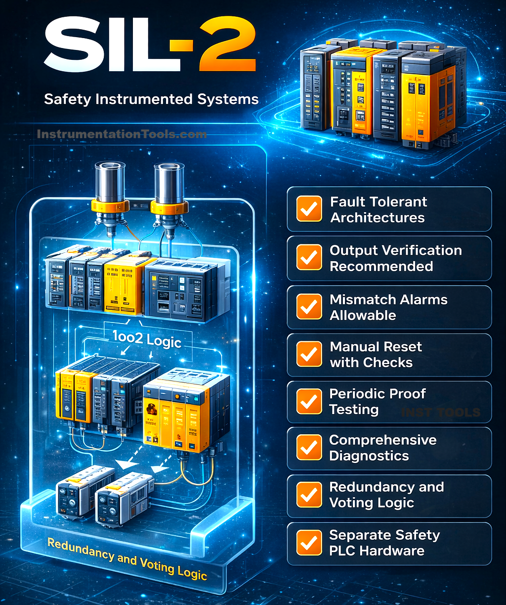
- SIL-2 follows and moves ahead of the basic principles written for SIL-1. First of all, instead of only a single sensor, there are two or three sensors. In that, voting logic will be implemented, like 1oo2 or 2oo3 voting. So, in the case of 2oo3 voting, the nod must be given from any 2 sensors to conclude an alarm, instead of taking a nod only from a single sensor.
- Building on the fault diagnostics used in SIL-1, SIL-2 introduces additional diagnostic mechanisms such as mismatch detection between redundant sensors and monitoring the availability of each measurement channel. In voting architectures like 2oo3, the system continuously evaluates readings from all three sensors and checks whether at least two values agree within a defined tolerance band. These two matching values are used for the voting decision, while the third channel is identified as faulty or suspect. Although the sensors used in 2oo3 configurations are often similar in type and principle of operation, care must be taken in their installation to minimize common-cause failures. If fewer than two valid sensor readings are available, the voting logic is no longer satisfied, and the safety function must transition to a safe state.
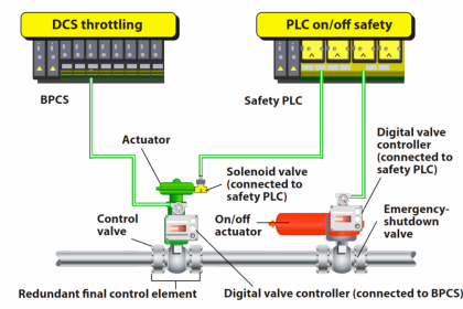
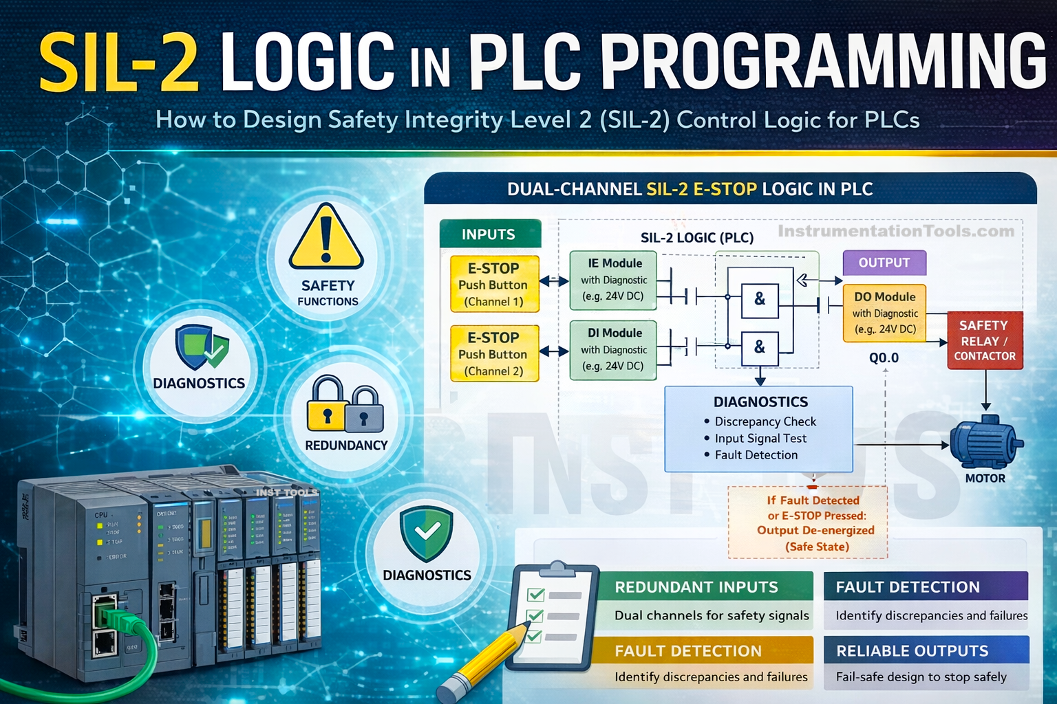
- Instead of a standard PLC, it is compulsory to use a safety PLC for SIL-2 applications. These PLCs provide certified safety runtime, dual processors/lockstep CPUs, internal diagnostics, and TUV certification. All the critical IOs too should be fail-safe, and not normal ones, with pre-channel diagnostics, line monitoring, channel loss detection, and module internal fault detection. Apart from software logic for voting, AI channels must be separate, terminal blocks must be separate, and cable routing should be done independently. All the hardware diagnostics in the module must be enabled.
How to Develop SIL-2 Logic for Safety PLCs?
- Before starting any programming, just remember that you have to consider voting logic. So accordingly, you have to design the same logic in a repeated manner for all the sensors. Also, from a programming point of view, in a safety PLC, consider the following points: SIL-2 logic runs in a dedicated safety task, no shared tags with standard logic, no indirect addressing, and no complex state machines.
- For a trip condition, if 2oo3 voting is used, use AND gate logic. Voting ensures the safety function works despite one faulty channel. For example, refer to the following code:
Trip_Condition :=
(PT1_Trip AND PT2_Trip) OR
(PT2_Trip AND PT3_Trip) OR
(PT1_Trip AND PT3_Trip);
- The next logic to implement is mismatch detection. SIL-2 must detect dangerous disagreement. The simple method is to subtract one value from the other, and then compare the result with an allowed drift set value. If the difference goes beyond this value, then it means the sensors are not giving correct results, and a diagnostic fault must be generated to trip the system or continue as per the design specifications of the control logic for the next step to be done.
- Then, as voting works on redundancy, redundancy checks too must be done continuously. So, in 2oo3 voting, if 2 sensors are not responding, then a redundancy fault must be generated immediately to trip the system or continue as per the design specifications of control logic for the next step to be done.
- It is also necessary to take feedback on the outputs, to check whether they are actually working or not. So, if you do not receive any feedback from the output for a certain small delay, then a fault alarm must be generated.
Apart from these special points, all the logic must be written in the same way as SIL-1. In this way, we saw how to write SIL-2 logic in PLC programming.