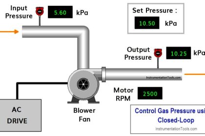
Protective instruments and alarms in industrial plants are provided with adjustable setpoints where specific actions are either automatically initiated, prohibited, or alarmed.
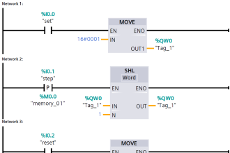
Setpoints and Alarms

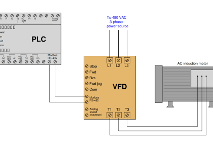
Image courtesy : iautomatyka
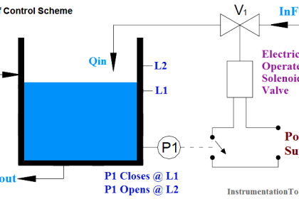
For example, pressure sensors typically are installed on main steam lines to measure steam pressure. These sensors initiate corrective action if the steam pressure decreases to the predetermined and preset value that would result, for example, from a steam line break.
Setpoints (e.g., pressure, differential pressure, flow, level, temperature) correspond to certain provisions of technical specifications that have been incorporated into the system.
The single most prevalent reason for the drift of a measured parameter out of compliance with a technical specification is the selection of a setpoint that does not allow a sufficient margin between the setpoint and the technical specification limit to account for inherent instrument inaccuracy, expected vibration, and minor calibration variations.
In some cases, the setpoint selected was numerically equal to the technical specification limit and stated as an absolute value, thus leaving no apparent margin for error. In other cases, the setpoint was so close to the upper or lower limit of the instrument’s range that the instrument drift placed the setpoint beyond the instrument’s range, thus nullifying the trip function.
Other causes for drift of a parameter out of conformity with a technical specification have been instrumentation design inadequacies and questionable calibration procedures.
Definitions
The following terms are listed with the definitions :
- Instrument accuracy – the degree to which an indicated value conforms to an accepted standard value or a true value.
- DrIft – a change in the input-output relationship of an instrument over a period of time.
- Margin – the difference between a limiting condition and an operating condition.
- Range – the region within which a quantity is measured, received, or transmitted.
- Safety limit – a limit on an important process variable that is necessary to reasonably protect the integrity of physical barriers that guard against uncontrolled release of radioactivity.
- Setpoint – a predetermined level at which a bistable device changes state to indicate that the quantity under surveillance has reached the selected value.
- Span – the algebraic difference between the upper and lower limits of the range.
- Technical specification limit – the maximum limit prescribed on an important process variable for safe operation.
Systems important to safety-those systems that are necessary to ensure
- The integrity of the different units of plant,
- The capability to shut down the plant and maintain it in a safe condition, or
- The capability to prevent or mitigate the consequences of accidents that could result in potential damage to the plant assets and personnel.
The following are applicable to instruments in systems important to safety:
The setpoints should be established with sufficient margin between the technical specification limits for the process variable and the nominal trip setpoints to allow for
- The inaccuracy of the instrument,
- Uncertainties in the calibration, and
- Instrument drift that could occur during the interval between calibrations.
All setpoints should be established in that portion of the instrument span which ensures that the accuracy, as required by regulatory position 4 below, is maintained. Instruments should be calibrated so as to ensure the required accuracy at the setpoint.
The range selected for the instrumentation should encompass the expected operating range of the process variable being monitored to the extent that saturation does not negate the required action of the instrument.
The accuracy of all setpoints should be equal to or better than the accuracy assumed in the safety analysis, which considers the ambient temperature changes, vibration, and other environmental conditions.
The instruments should not anneal, stress relieve, or work harden under design conditions to the extent that they will not maintain the required accuracy. Design verification of these instruments should be demonstrated.
Instruments should have a securing device on the setpoint adjustment mechanism unless it can be demonstrated by analysis or test that such devices will not aid in maintaining the required setpoint accuracy and minimizing setpoint changes.
The securing device should be designed so that it can be secured or released without altering the setpoint and .should be under administrative control.
The assumptions used in selecting the setpoint values in regulatory position and the minimum margin with respect to the limiting safety system settings, setpoint rate of deviation (drift rate), and the relationship of drift rate to testing interval (if any) should be documented.
If you liked this article, then please subscribe to our YouTube Channel for PLC and SCADA video tutorials.
You can also follow us on Facebook and Twitter to receive daily updates.
Read Next:
- What is Feedforward Control?
- PID Controller Functions
- Limit, Selector, and Override controls
- Multimeter & Megger Principle
- Practical Calibration Standards