In the world of PLC automation, the Timer is an important component in controlling the time of a program. By using a timer, we can control the time a device or system should be active or inactive. This article will discuss a simple application of a Timer, there are three lights that will turn On sequentially and will turn Off sequentially with a time interval of 10 seconds using Omron CX-programmer PLC software.
Sequential Control of Three Lights with Reset
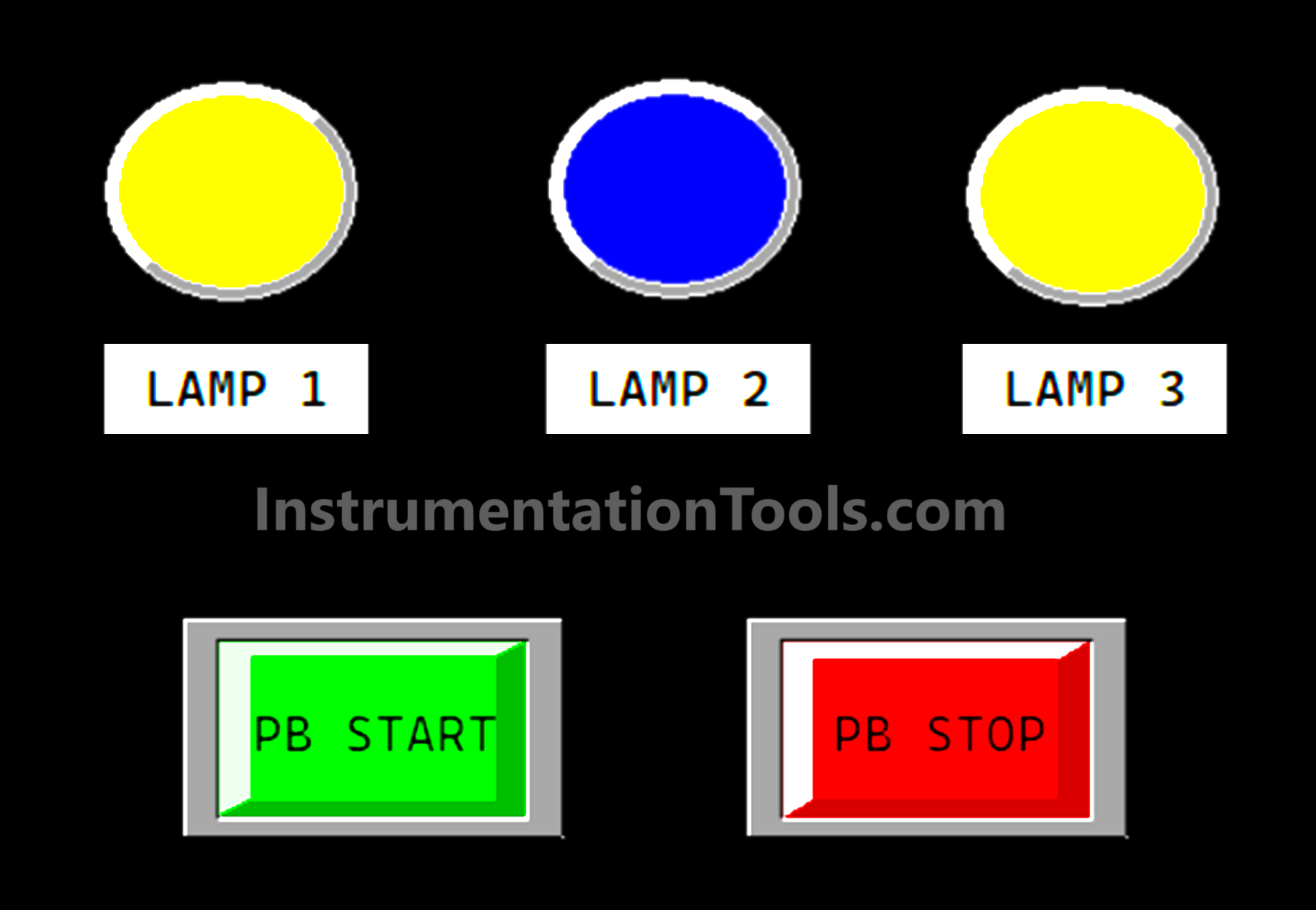
In this PLC example, the following buttons are used.
- The PB_START (0.00) button is used to turn ON the system.
- The PB_STOP (0.01) button is used to turn OFF the system.
This program has 2 sequences:
SEQUENCE 1
This sequence will Run when the system is turned On, namely when the PB_START (0.00) button is Pressed.
When Sequence-1 has started Lamp 1 LAMP_1 (100.01) will be ON.
10 seconds after that, Lamp 2 LAMP_2 (100.02) will turn ON, and 10 seconds later, Lamp 3 LAMP_3(100.03) will also turn ON.
When Sequence-1 is running, the value in memory word SEQUENCE (D0) will be “1” and will be set to zero “0” when Lamp 1 LAMP_1 (100.01), Lamp 2 LAMP_2 (100.02), and Lamp 3 LAMP_3 (100.03) has turned ON.
SEQUENCE 2
This sequence will Run when the system is turned OFF, namely when the PB_STOP (0.01) button is Pressed.
Sequence-2 can only be executed when Lamp 1 LAMP_1 (100.01), Lamp 2 LAMP_2 (100.02), and Lamp 3 LAMP_3 (100.03) are all ON.
When Sequence-2 has started Lamp 3 LAMP_3 (100.03) will be OFF.
10 seconds after that, Lamp 2 LAMP_2 (100.02) will turn OFF and 10 seconds later, Lamp 1 LAMP_1(100.01) will also turn OFF.
When Sequence-2 is running, the value in memory word SEQUENCE (D0) will be “2” and will be set to zero “0” when Lamp 1 LAMP_1 (100.01), Lamp 2 LAMP_2 (100.02), and Lamp 3 LAMP_3 (100.03) has turned OFF.
Addressing of Program
| Comment | Input (I) | Output (Q) | Memory Word | Memory Bits | Timer |
| PB_START | 0.00 | ||||
| PB_STOP | 0.01 | ||||
| LAMP_1 | 100.01 | ||||
| LAMP_2 | 100.02 | ||||
| LAMP_3 | 100.03 | ||||
| TIMER_1 | T0000 | ||||
| TIMER_2 | T0001 | ||||
| TIMER_3 | T0002 | ||||
| TIMER_4 | T0003 | ||||
| SEQUENCE_1 | W0.00 | ||||
| SEQUENCE_2 | W0.01 | ||||
| SEQUENCE | D0 |
PLC Timer Example
RUNG 0 (START SYSTEM)
In this Rung, when the PB_START (0.00) button is pressed, the value in the memory word SEQUENCE (D0) becomes “1”, so the system will Run on Sequence-1.
RUNG 1 (STOP SYSTEM)
In this Rung, when the PB_STOP (0.01) button is Pressed and the NO contact of Output LAMP_3 (100.00) is ON, the value in the memory word SEQUENCE (D0) becomes “2”, so the system will Run in Sequence-2.
RUNG 2 (SEQUENCE 1)
If the value in the memory word SEQUENCE (D0) is equal to “1”, then the memory bit SEQUENCE_1 (W0.00) will be in the HIGH state and the Timer TIMER_1 (T0000) will Start counting up to 10 seconds.
When Timer TIMER_1 (T0000) has finished counting, the NO contact of Timer TIMER_1 (T0000) will be in the HIGH state and Timer TIMER_2 (T0001) will count up to 10 seconds.
RUNG 3 (SEQUENCE 2)
If the value in the memory word SEQUENCE (D0) is equal to “2”, then the memory bit SEQUENCE_2 (W0.01) will be in the HIGH state and Timer TIMER_3 (T0002) will Start counting up to 10 seconds.
When Timer TIMER_3 (T0002) has finished counting, the NO contact of Timer TIMER_3 (T0002) will be in the HIGH state and Timer TIMER_4 (T0003) will Start counting up to 10 seconds.
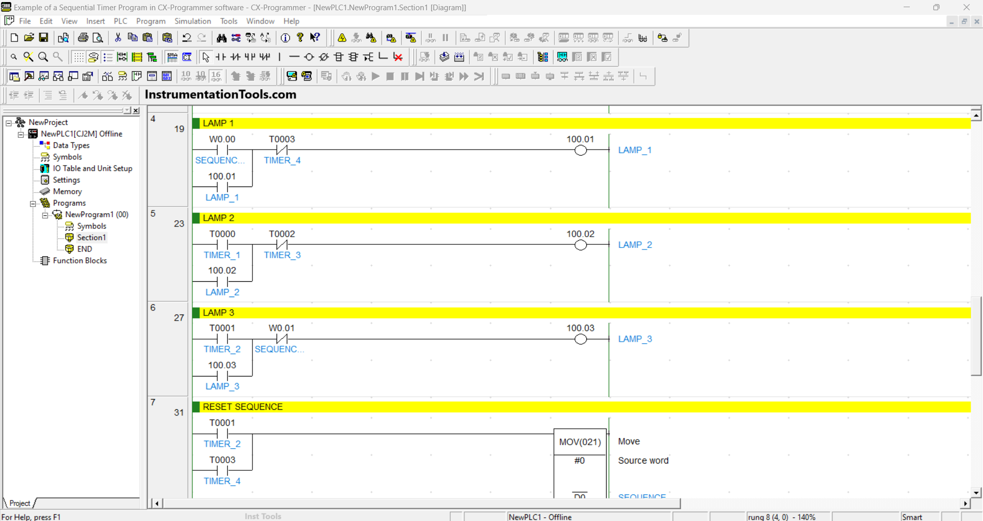
RUNG 4 (LAMP 1)
In this Rung, if contact NO of memory bit SEQUENCE_1 (W0.00) in the HIGH state, then Output LAMP_1 (100.01) will be ON. Because it uses Latching, the LAMP_1 (100.01) Output will remain in the ON state even though the NO contact of memory bit SEQUENCE_1 (W0.00) in the LOW state.
The LAMP_1 (100.01) Output will be OFF if the NC contact of the Timer TIMER_4 (T0003) is in the HIGH state.
RUNG 5 (LAMP 2)
In this Rung, when the NO contact of Timer TIMER_1 (T0000) is in the HIGH state, the Output LAMP_2 (100.02) will be ON. Because it uses Latching, the LAMP_2 (100.02) Output will remain in the ON state even though the NO contact of Timer TIMER_1 (T0000) in the LOW state.
The LAMP_2 (100.02) Output will be OFF if the NC contact of Timer TIMER_3 (T0002) is in the HIGH state.
RUNG 6 (LAMP 3)
In this Rung, when the NO contact of Timer TIMER_2 (T0001) is in the HIGH state, the Output LAMP_3 (100.03) will be ON. Because it uses Latching, the LAMP_3 (100.03) Output will remain in the ON state even though the NO contact of Timer TIMER_2 (T0001) in the LOW state.
The LAMP_3 (100.03) Output will be OFF if the NC contact of memory bit SEQUENCE_2 (W0.01) is in the HIGH state.
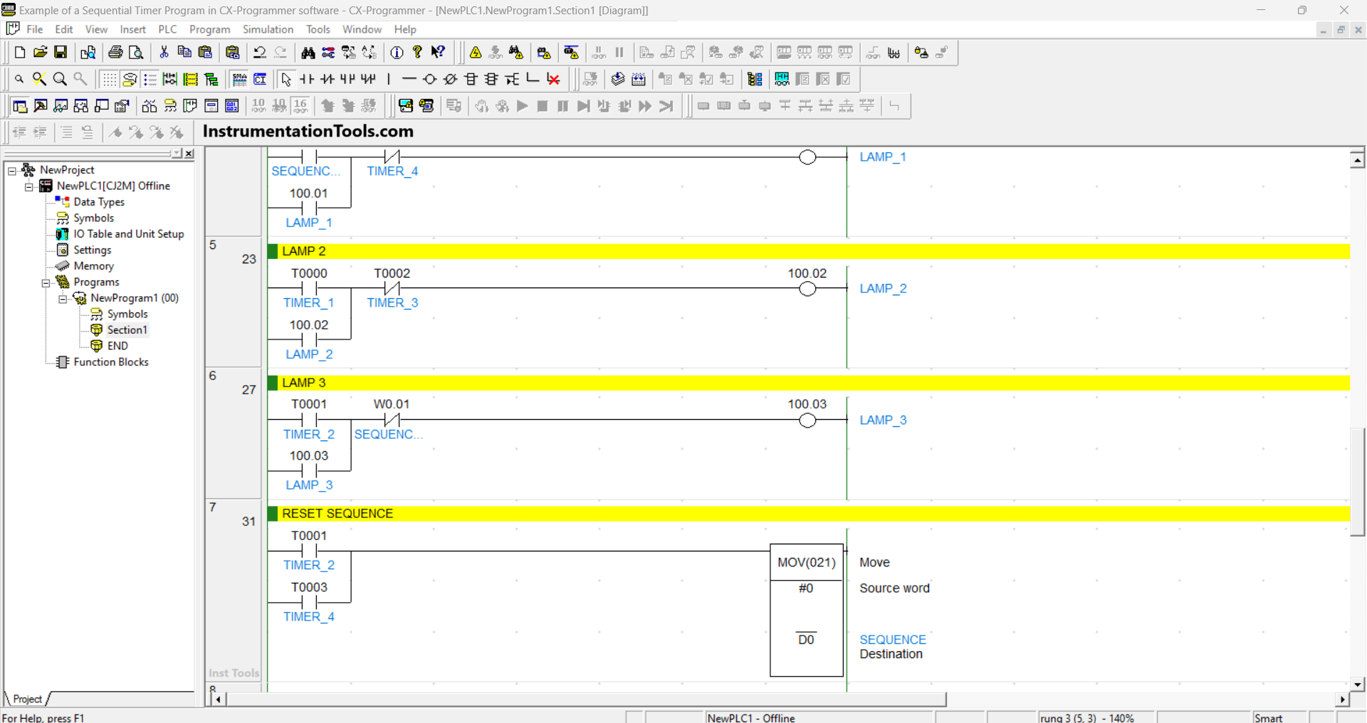
RUNG 7 (RESET SEQUENCE)
In this Rung, when the NO contact of Timer TIMER_2 (T0001) or Timer TIMER_4 (T0003) in the HIGH state, the memory word SEQUENCE (D0) will be reset to zero “0”. Because the MOV(021) instruction moves the zero value to the memory word SEQUENCE (D0).
Read Next:
- Simple Conveyor Control PLC Program Example
- Create a User-Defined Function Block in Codesys
- Structured Text PLC Example for Motor Interlock
- Allen Bradley PLC to PLC Communication Tutorial
- PLC Packing Machine Control System Program