In PLC programming, one of the most highly advanced languages is structured text. It is similar to the Pascal language that we use in IT programming. Due to this, you can execute highly difficult and complex codes in a very short length and speed. In TIA Portal software (Siemens), this language is termed SCL or structured control language. If you are new to this language and are using the TIA Portal, then this series of posts will help you learn it properly. In this post, we will see how to start writing SCL language in the TIA Portal.
SCL Language in Siemens Tia Portal
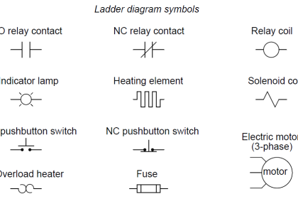
As discussed, SCL stands for structured control language. It is based on IEC 1131-3. For simplicity, we will compare this language with ladder logic for your understanding. As compared to ladder logic where you place elements or symbols like NO, NC, COIL, SET, RESET, etc.
SCL language comprises expressions, value assignments, and operators. This means, you have to write this in statement syntax. Due to this, you can easily create branches, jumps, and loops. So, complex applications like mathematical calculations and data analysis are mostly written in this language by PLC programmers. Let us jump further by comparing a simple start-stop logic written in ladder language with SCL language.
SCL Programming for Beginners
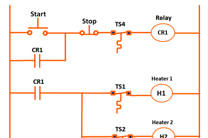
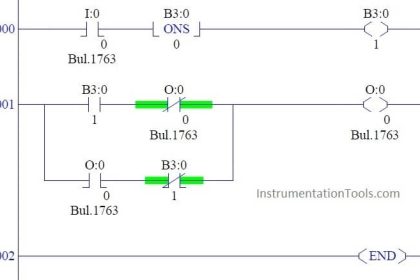
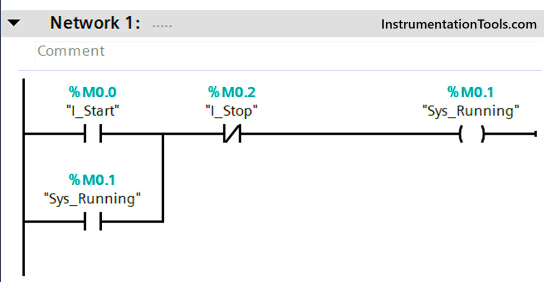
Refer to the below image. The code is written in Ladder language. If you see, the following elements are used – two NO contacts, one NC contact, and one normal coil. The logic written is – if the variable I_Start is on or the variable Sys_Running is on and the variable I_Stop is off, then the variable Sys_Running turns on. If any of the conditions goes false, then the output too will turn off.
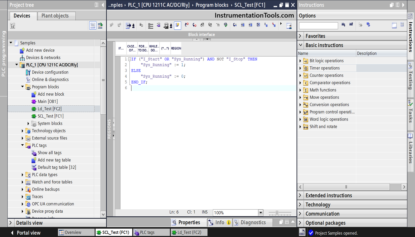
Now, before writing the code in SCL language, just read our logic written. This same logic is written in statement language as shown below. The language chosen is SCL.
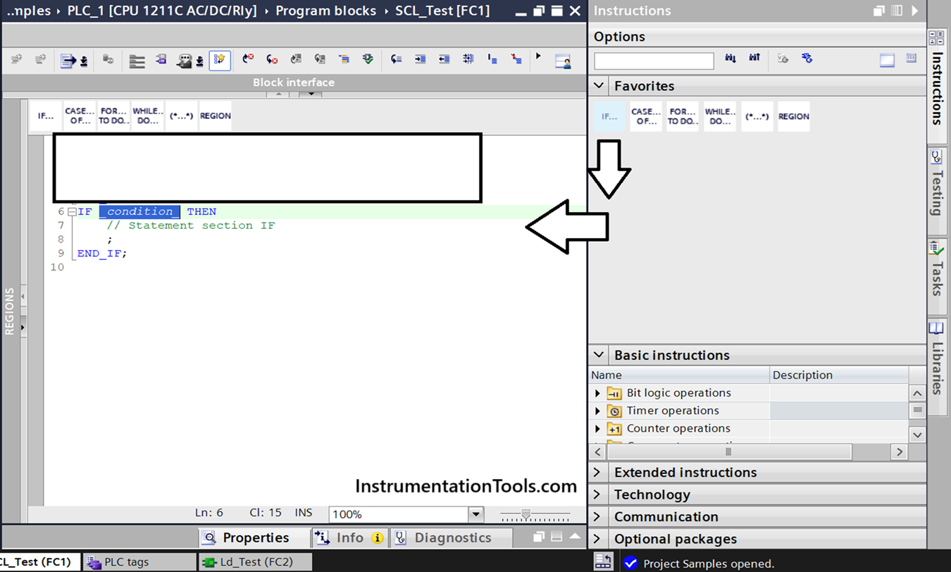
In the favorites tab, click if and drag and drop it as shown below (You can also write it manually, but this is done for simplicity and if you do not know the syntax). What do you see? There are two elements – one logic, one condition, and one statement. The logic refers to the if-else statement here. If you correlate this with ladder logic, if the conditions are true, then the output turns on. So here, the output is replaced by a statement and the conditions remain as it is.
Now, let us understand the logic written by seeing the below image. We will recall the logic once again – if the variable I_Start is on or the variable Sys_Running is on and the variable I_Stop is off, then the variable Sys_Running turns on. If any of the conditions goes false, then the output too will turn off. As you can see below, there are three types of elements used – expression, operator and value assignment.
An expression means a group of variables or a single variable written in a style, which returns a value during runtime. They are executed from left to right and also sometimes involve the use of brackets. Each line thus represents an expression. An operator can be logical, arithmetic, relational, reference, or miscellaneous, determined by its symbol. It is responsible for performing a function. A value assignment is similar to a write logic, where we write a value to a tag. So, the flow for writing an SCL logic is – use operators inside an expression, use this expression as either a condition or statement, and use value assignments for writing a value.
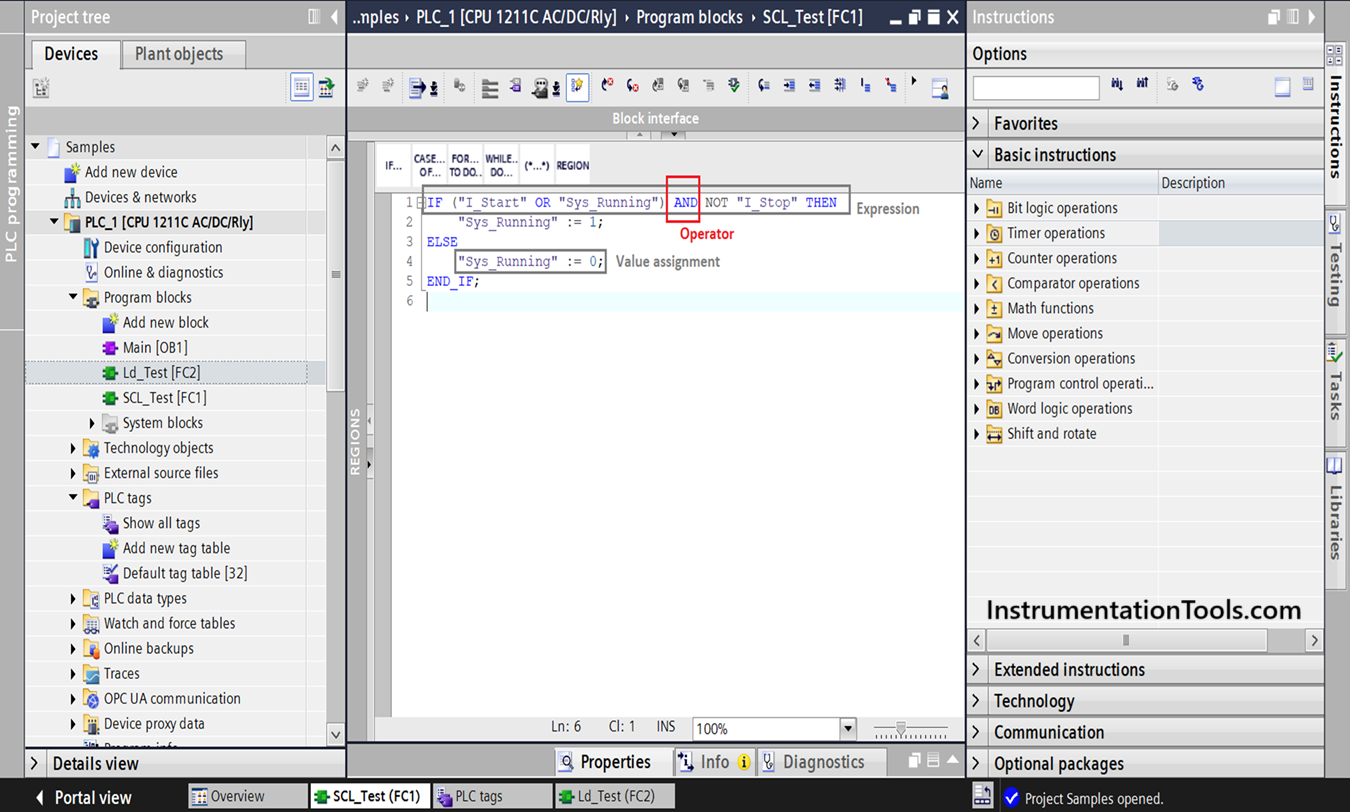
As you can see below, we write the whole condition in an if style. In the ladder logic, the two NO elements in parallel are written here as an OR operator, which has the same meaning. They are then enclosed in a bracket, meaning they work in a group. Then, the NC element placed in series is written here as an AND operator, which has the same meaning. The whole condition is terminated by THEN, meaning to start an action. Afterwards, the normal coil is written here in value assignment style, by moving a value ‘1’ in the variable. The left-hand side of := denotes the variable to be written, and the right-hand side of := denotes the value to be written.
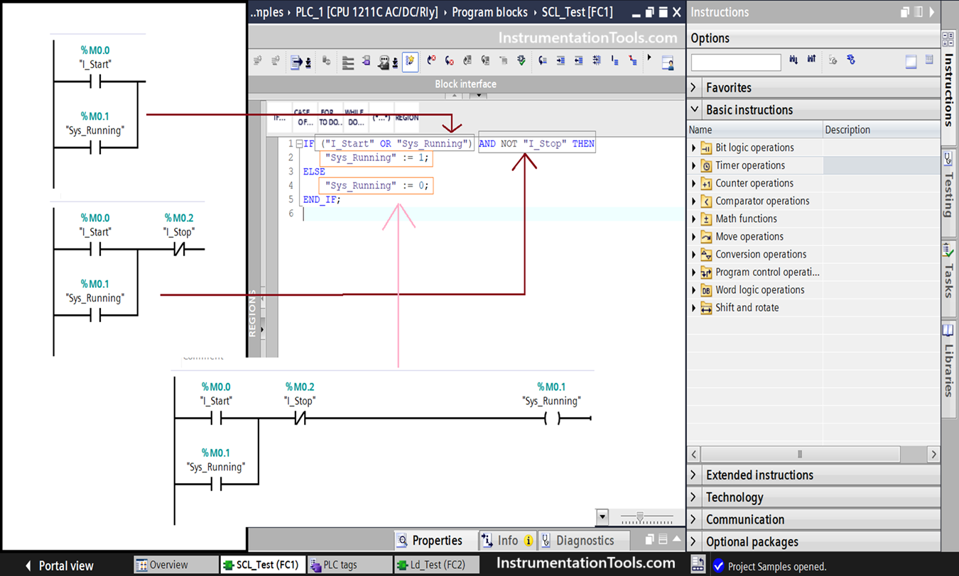
As in the ladder logic, if any of the conditions fails, then the output turns off. So, we then continue with the ELSE keyword. Afterwards, the normal coil is written here in value assignment style, by moving a value ‘0’ in the variable. Then, we terminate the whole if-else logic with END_IF keyword. One thing to note is that conditions do not require a ; in the end, but a value assignment requires a ; in the end of the line. Just now read the whole logic from start to end, and you can see clearly how it matches the ladder logic.
Let me simplify your doubt more as below:
- The first line expression is a condition.
- The second line expression is a value assignment or statement.
- The third line expression is a keyword for moving further to write a second value if the condition is not true.
- The fourth line expression is a value assignment or statement.
- The fifth line expression is a keyword for ending the whole logic.
As we see other articles further, you will see how SCL is relatively easy to write. In the next post, we will see the arithmetic, relational and logical expressions that can be used, which will help us to write logic further.
Read Next:
- PLC Instruction List Program for Basic Instructions
- How to do Scaling for Analog Input in RSLogix 500?
- PLC Light Sequence Control using Bit Shift Registers
- PLC Instruction List for Motor Reverse and Forward
- Timer-Based Sequential PLC Program with One Button