Inst ToolsInst ToolsInst Tools
  • Courses
  • Automation
    • PLC
    • Control System
    • Safety System
    • Communication
    • Fire & Gas System
  • Instrumentation
    • Design
    • Pressure
    • Temperature
    • Flow
    • Level
    • Vibration
    • Analyzer
    • Control Valve
    • Switch
    • Calibration
    • Erection & Commissioning
  • Interview
    • Instrumentation
    • Electrical
    • Electronics
    • Practical
  • Q&A
    • Instrumentation
    • Control System
    • Electrical
    • Electronics
    • Analog Electronics
    • Digital Electronics
    • Power Electronics
    • Microprocessor
  • Request
Search
  • Books
  • Software
  • Projects
  • Process
  • Tools
  • Basics
  • Formula
  • Power Plant
  • Root Cause Analysis
  • Electrical Basics
  • Animation
  • Standards
  • 4-20 mA Course
  • Siemens PLC Course
Reading: Rotameter Working Principle and Animation
Share
Font ResizerAa
Inst ToolsInst Tools
Font ResizerAa
  • Courses
  • Design
  • PLC
  • Interview
  • Control System
Search
  • Courses
  • Automation
    • PLC
    • Control System
    • Safety System
    • Communication
    • Fire & Gas System
  • Instrumentation
    • Design
    • Pressure
    • Temperature
    • Flow
    • Level
    • Vibration
    • Analyzer
    • Control Valve
    • Switch
    • Calibration
    • Erection & Commissioning
  • Interview
    • Instrumentation
    • Electrical
    • Electronics
    • Practical
  • Q&A
    • Instrumentation
    • Control System
    • Electrical
    • Electronics
    • Analog Electronics
    • Digital Electronics
    • Power Electronics
    • Microprocessor
  • Request
Follow US
All rights reserved. Reproduction in whole or in part without written permission is prohibited.
Inst Tools > Blog > Animation > Rotameter Working Principle and Animation

Rotameter Working Principle and Animation

A rotameter is a device that measures the flow rate of liquid or gas in a closed tube. It is one type of variable area flow meter.

Last updated: October 31, 2023 12:22 pm
Editorial Staff
Animation Flow Measurement How It Works
No Comments
Share
5 Min Read
SHARE

A rotameter is a device that measures the flow rate of liquid or gas in a closed tube.

Contents
RotameterAdvantages of RotameterDisadvantages of Rotameter

Rotameter belongs to a class of meters called variable area meters, which measure flow rate by allowing the cross-sectional area the fluid travels through, to vary, causing a measurable effect.

Rotameter
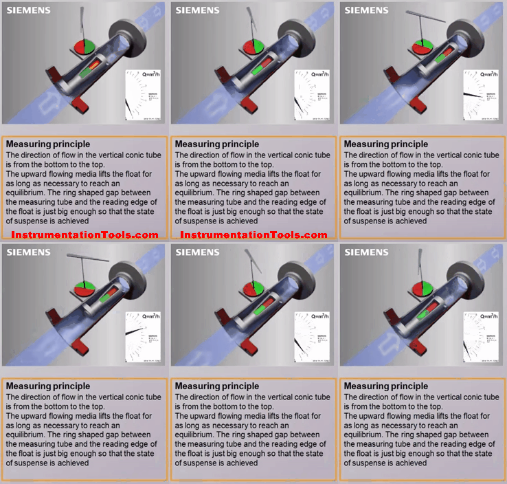
Variable Area Flow meter Working Animation

A rotameter consists of a tapered tube, typically made of glass with a ‘float’, made either of anodized aluminum or ceramic, actually a shaped weight, inside that is pushed up by the drag force of the flow and pulled down by gravity.

The drag force for a given fluid and float cross-section is a function of flow speed squared only.

A higher volumetric flow rate through a given area increases flow speed and drag force, so the float will be pushed upwards.

However, as the inside of the rotameter is cone-shaped (widens), the area around the float through which the medium flows increases, and the flow speed and drag force decrease until there is mechanical equilibrium with the float’s weight.

Floats are made in many different shapes, with spheres and ellipsoids being the most common. The float may be diagonally grooved and partially colored so that it rotates axially as the fluid passes.

This shows if the float is stuck since it will only rotate if it is free. Readings are usually taken at the top of the widest part of the float; the center for an ellipsoid, or the top for a cylinder. Some manufacturers use a different standard.
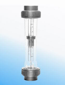
Rotameter Working

The “float” must not float in the fluid: it has to have a higher density than the fluid, otherwise, it will float to the top even if there is no flow.

The mechanical nature of the measuring principle provides a flow measurement device that does not require any electrical power. If the tube is made of metal, the float position is transferred to an external indicator via a magnetic coupling.

This capability has considerably expanded the range of applications for the variable area flow meter since the measurement can observed remotely from the process or used for automatic control.

Advantages of Rotameter

  • A rotameter requires no external power or fuel, it uses only the inherent properties of the fluid, along with gravity, to measure flow rate.
  • A rotameter is also a relatively simple device that can be mass-manufactured out of cheap materials, allowing for its widespread use.
  • Since the area of the flow passage increases as the float moves up the tube, the scale is approximately linear.
  • Clear glass is used which is highly resistant to thermal shock and chemical action.

Disadvantages of Rotameter

  • Due to its use of gravity, a rotameter must always be vertically oriented and right way up, with the fluid flowing upward.
  • Due to its reliance on the ability of the fluid or gas to displace the float, graduations on a given rotameter will only be accurate for a given substance at a given temperature. The main property of importance is the density of the fluid; however, viscosity may also be significant. Floats are ideally designed to be insensitive to viscosity; however, this is seldom verifiable from manufacturers’ specifications. Either separate rotameters for different densities and viscosities may be used, or multiple scales on the same rotameter can be used.
  • Due to the direct flow indication the resolution is relatively poor compared to other measurement principles. Readout uncertainty gets worse near the bottom of the scale. Oscillations of the float and parallax may further increase the uncertainty of the measurement.
  • Since the float must be read through the flowing medium, some fluids may obscure the reading. A transducer may be required for electronically measuring the position of the float.
  • Rotameters are not easily adapted for reading by machine; although magnetic floats that drive a follower outside the tube are available.
  • Rotameters are not generally manufactured in sizes greater than 6 inches/150 mm, but bypass designs are sometimes used on very large pipes.

If you liked this article, then please subscribe to our YouTube Channel for Instrumentation, Electrical, PLC, and SCADA video tutorials.

You can also follow us on Facebook and Twitter to receive daily updates.

Read Next:

  • Variable Flow Meter Theory
  • Calibrate Different Flow Meters
  • Turbine Flow Meter Verification
  • Calibration Turbine Flow Meter
  • Orifice Flow Meter Specification
Don't Miss Our Updates
Be the first to get exclusive content straight to your email.
We promise not to spam you. You can unsubscribe at any time.
Invalid email address
You've successfully subscribed !

Continue Reading

Online Simulation
Electrical Switches Working Animation
Phase Watcher Multiphase Flow Meter (MPFM) Procedure
PLC Sinking and Sourcing Explanation
V Cone Flow Meter – Principle, Advantages, Disadvantages
Dall Tube Flow Meter – Principle, Advantages, Disadvantages
Share This Article
Facebook Whatsapp Whatsapp LinkedIn Copy Link
Share
Leave a Comment

Leave a Reply Cancel reply

Your email address will not be published. Required fields are marked *

Stay Connected

128.3kFollowersLike
69.1kFollowersFollow
210kSubscribersSubscribe
38kFollowersFollow

Categories

Explore More

Oscillating Piston Flow Meters Working Principle
Classification of Flow Measurement Techniques
Particle Image Velocimetry (PIV) Principle
Solenoid Valve Working Animation
Probe Type GWR Level Transmitter Working Animation
Open Loop and Closed Loop Animation
Network Switch Port Allocation Details
Area Velocity Flow Meter Principle

Keep Learning

Flow Meters Troubleshooting

Turbine Flow Meters Troubleshooting

Water Cut Meter

What is Water Cut Meter?

Venturi Flow Measurement Principle

Why Flow is Directly Proportional to the Square Root of DP?

Rotameter

What is a Variable Area Flow Meter?

orifice-plate

Orifice Plate Turndown ratio

Metal tube Variable Area Flowmeters Principle

Metal Tube Variable Area Flow Meters Principle

Pressure Temperature Compensation Flow Measurement

Pressure Temperature Compensation Flow Measurement

Tilt Level Switch Theory

Tilt Level Switch Working Principle

Learn More

Purpose of Emergency Shutdown (ESD) System

Purpose of Emergency Shutdown (ESD) System

Gearbox within week Failing Journal Bearing upset Plant Operations

Gearbox within week Failing Journal Bearing upset Plant Operations

Distribution transformer

Different Types of Transformers

What is Hydraulics

What is Hydraulics?

How to do Control Valve Sizing

How do you do control valve sizing in Layman’s terms?

Anti Surge Controller Theory

Anti Surge Controller Working Principle

Pressure Gauges with Diaphragm Sensor Principle

Pressure Gauges with Diaphragm Sensor Principle

Industrial Automation Acronyms

111 Industrial Automation Acronyms Questions and Answers

Menu

  • About
  • Privacy Policy
  • Copyright

Quick Links

  • Learn PLC
  • Helping Hand
  • Part Time Job

YouTube Subscribe

Follow US
All rights reserved. Reproduction in whole or in part without written permission is prohibited.
Welcome Back!

Sign in to your account

Username or Email Address
Password

Lost your password?