By using this site, you agree to the Privacy Policy and Terms of Use.
Accept
Inst ToolsInst ToolsInst Tools
  • Ask
  • Courses
  • Videos
  • Q & A
    • Interview
      • Instrumentation
      • Electronics
      • Electrical
      • Practical Questions
    • MCQ
      • Instrumentation MCQ
      • Electrical MCQ
      • Electronics MCQ
      • Control Systems MCQ
      • Analog Electronics MCQ
      • Digital Electronics MCQ
      • Power Electronics MCQ
      • Microprocessor MCQ
      • Multiple Choice Questions
  • EE
    • Electronics
      • Electronics Q & A
      • Electronic Basics
      • Electronic Devices & Circuits
      • Electronics Animation
      • Digital Electronics
    • Electrical
      • Electrical Basics
      • Electrical Q & A
      • Power Electronics
      • Electrical Machines
      • Electrical Animation
      • Power Systems
      • Switchgear & Protection
      • Transmission & Distribution
  • Measure
    • Control Valves
    • Calibration
    • Temperature
    • Pressure
    • Flow
    • Level
    • Analyzers
    • Switches
    • Vibration
    • Solenoid Valve
  • Control
    • PLC Tutorials
    • Control Systems
    • Safety Instrumented System (SIS)
    • Communication
    • Fire & Gas System
  • More
    • Design
    • Tools
    • Animation
    • Basics
    • Formulas
    • Standards
    • TextBooks
    • Common
    • Software
    • Excel Tools
    • Erection & Commissioning
    • Process Fundamentals
    • Videos
    • Books
Search
All rights reserved. Reproduction in whole or in part without written permission is prohibited.
Reading: How does a Redundant Controller comes in line when the Main Controller fails?
Share
Notification Show More
Font ResizerAa
Inst ToolsInst Tools
Font ResizerAa
  • Ask
  • Courses
  • Videos
  • Q & A
  • EE
  • Measure
  • Control
  • More
Search
  • Ask
  • Courses
  • Videos
  • Q & A
    • Interview
    • MCQ
  • EE
    • Electronics
    • Electrical
  • Measure
    • Control Valves
    • Calibration
    • Temperature
    • Pressure
    • Flow
    • Level
    • Analyzers
    • Switches
    • Vibration
    • Solenoid Valve
  • Control
    • PLC Tutorials
    • Control Systems
    • Safety Instrumented System (SIS)
    • Communication
    • Fire & Gas System
  • More
    • Design
    • Tools
    • Animation
    • Basics
    • Formulas
    • Standards
    • TextBooks
    • Common
    • Software
    • Excel Tools
    • Erection & Commissioning
    • Process Fundamentals
    • Videos
    • Books
Follow US
All rights reserved. Reproduction in whole or in part without written permission is prohibited.
Inst Tools > Blog > Control Systems > How does a Redundant Controller comes in line when the Main Controller fails?

How does a Redundant Controller comes in line when the Main Controller fails?

Last updated: December 19, 2019 9:44 pm
Editorial Staff
Control Systems Guest Articles
1 Comment
Share
2 Min Read
SHARE

How does a Redundant Controller comes in line when the Main Controller fails in the distributed control system (DCS)?

The Processor Card performs calculations and control computation. In case of Field Control Station (FCS) (simply we can assume as a System Cabinet with Processor cards & other IO cards) with duplexed configuration, there are two processor cards. One of the cards is in control status (main) and the other is in the standby status.

In case of FCS with duplexed configuration, both the processor cards perform control computation.

From the below figure, we have Left Processor Card and Right Processor Card. Again each processor card has two inbuilt processors or CPU, which perform the same control computation (optional feature, some cards may have only one, depends on manufacturer).

By Default, One Processor Card (say Right CPU) will be main and Other (Left) card is in Standby mode during Start-up.

All Inputs & outputs will be shared among the Two Processor Cards (Left & Right). The same program will be downloaded into both Cards (left & Right).

As per below figure, Both Left & Right Processor Cards have two Sub CPU’s inside. The two sub CPU’s in each Processor Card (Left or Right) executes same functions.

A comparator compares the computation results during each computation cycle of these CPU’s. If the results match computation is normal and the data is sent to locations such as the main memory and bus interface unit for further processing to take respective action. If the results do not match, the corresponding processor card will be stopped.

If the error occurs in the active (main) processor card, then switchover to standby card occurs without any interruption to live monitor/control of the plant.

main controller fails

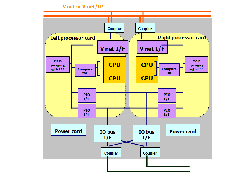
Image Courtesy : Yokogawa

Don't Miss Our Updates
Be the first to get exclusive content straight to your email.
We promise not to spam you. You can unsubscribe at any time.
Invalid email address
You've successfully subscribed !
PLC Program for Alarm Indication in Process Control
Interactions With Process Control Systems Philosophy
What is Wellhead Control Panel?
100+ Questions and Answers on Industrial Automation and Control
What is Instrument Hook Up Diagram ?
Share This Article
Facebook Whatsapp Whatsapp LinkedIn Copy Link
Share
1 Comment
  • Vivian says:
    February 19, 2018 at 6:22 am

    How does it know which processor is giving the error signal ?

    Reply

Leave a Reply Cancel reply

Your email address will not be published. Required fields are marked *

Stay Connected

128.3kFollowersLike
69.1kFollowersFollow
208kSubscribersSubscribe
38kFollowersFollow

Recent Comments

  • MIHARITSOA Aina Sitraka on Top Non-PLC Certification Courses for Automation Professionals
  • Vaishnavi on Free Instrumentation Course for Trainee Engineers
  • anuj kapoor on DCS Program to Maintain Draft in Furnace
  • anuj kapoor on IoT based Smart Boiler Control System with Cloud PLC and SCADA

Related Articles

Capacitive Field Effects on Conductors-4

Capacitive Coupling Effects

Why 4-20 mA Current Signal is used instead of Voltage Signal

Why 4-20 mA Current Signal is used instead of Voltage Signal?

Loop-powered 4-20 mA transmitter

Loop-powered 4-20 mA Transmitter Circuit Voltage drop

AI AO DI DO Signals

What are AI, AO, DI, and DO? – Definition, Examples, Purpose

Heat Exchanger Outlet Temperature Control

Heat Exchanger Temperature Control

Select Right Type of Controller

How to Select the Right Type of Controller

Functional Safety Terms in Industrial Automation

Functional Safety Terminology in Industrial Automation

Instrumentation Earthing

Instrumentation Earthing

More Articles

Calibration Instruments

Basics of Calibration

What is Chromatography

What is Chromatography ?

Difference between Fixed Area and Variable Area FlowMeters

Difference between Fixed Area & Variable Area FlowMeters

DC Motor Action

DC Motor Speed

Kiln

Kiln Inlet Gas Analyzer

Passing Control Valves Cause Yearly Losses

Passing Control Valves Cause Yearly Losses in Production Plant

MTech Project Ideas for Electronics and Electrical Engineering

100 MTech Project Ideas for Electronics and Electrical Engineering

Traces in TIA Portal

What is Trace Function in Tia Portal?

Follow US
All rights reserved. Reproduction in whole or in part without written permission is prohibited.
Welcome Back!

Sign in to your account

Username or Email Address
Password

Lost your password?