When performing heuristic tuning of a PID controller, it is important to be able to identify a condition where one or more of the “actions” (P, I, or D) is configured too aggressively for the process.
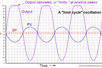
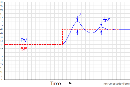
The characteristic indication of over-tuning is the presence of sinusoidal oscillations. At best, this means damped oscillations following a sudden setpoint or load change. At worst, this means oscillations that never decay:
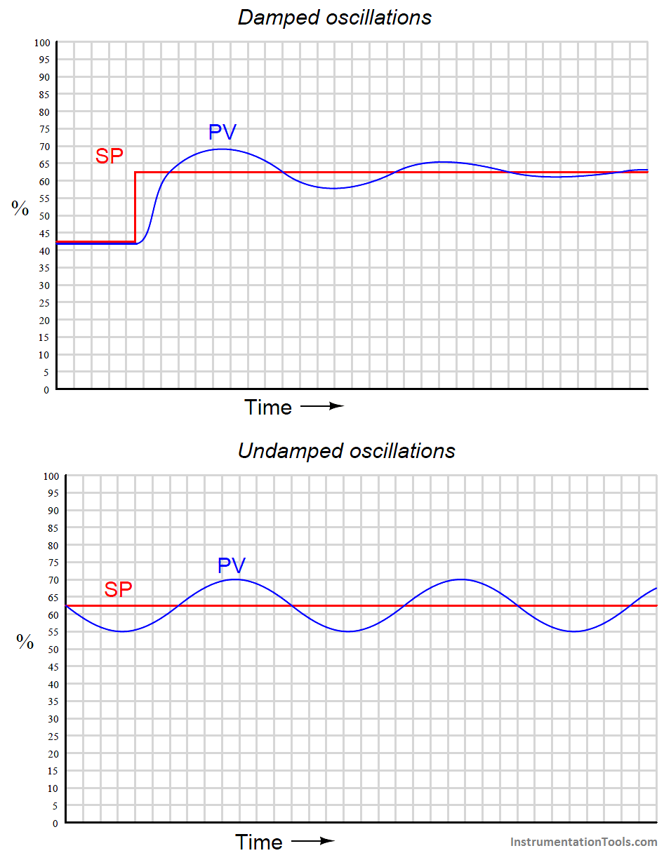
At this point, the question is: which action of the controller is causing this oscillation? We know all three actions (P, I, and D) are fully capable of causing process oscillation if set too aggressive, so in the lack of clarifying information it could be any of them (or some combination!).
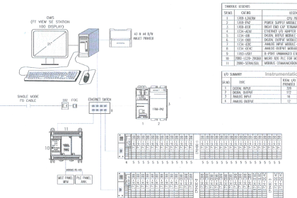
One clue is the trend of the controller’s output compared with the trend of the process variable (PV). Modern digital control systems all have the ability to trend manipulated variables as well as process variables, allowing personnel to monitor exactly how a loop controller is managing a process. If we compare the two trends, we may examine the phase shift between PV and output of a loop controller to discern what it’s dominant action is.
For example, the following trend graphs show the PV and output signals for a loop controller with proportional-dominant response. Both direct- and reverse-acting versions are shown:
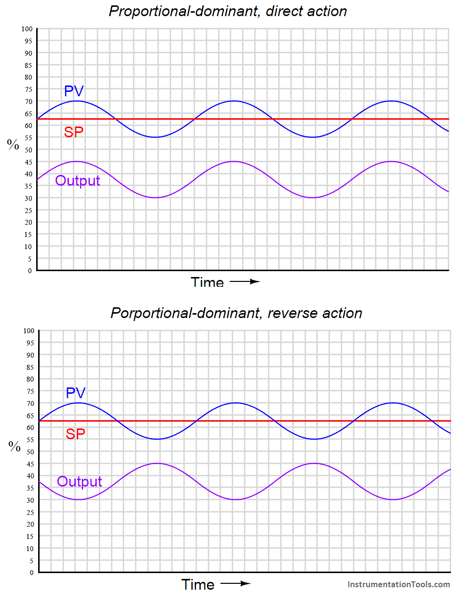
Since we know proportional action is immediate, there should be no phase shift (Note) between the PV and output waveforms. This makes sense from a mathematical perspective: if we substitute a sine function for the error variable in a proportional-only controller equation, we see that different gain values (Kp) simply result in an output signal of the same phase, just amplified or attenuated:
m = Kpe + b
m = Kp(sin t) + b
Note : For reverse-acting controllers, I am ignoring the obvious 180o phase shift necessary for negative feedback control when I say “no phase shift” between PV and output waveforms. I am also ignoring dead time resulting from the scanning of the PID algorithm in the digital controller. For some controllers, this scan time may be significant enough to see on a trend!
If ever you see a process oscillating like this (sinusoidal waveforms, with the PV and output signals in-phase), you know that the controller’s response to the process is dominated by proportional action, and that the gain needs to be reduced (i.e. increase proportional band) to achieve stability.
Integral and derivative actions, however, introduce phase shift between the PV waveform and the output waveform. The direction of phase shift will reveal which time-based action (either I or D) dominates the controller’s response and is therefore most likely the cause of oscillation.
For example, the following trend graph shows the PV and output signals for a loop controller with integral-dominant response. Both direct- and reverse-acting versions are shown:
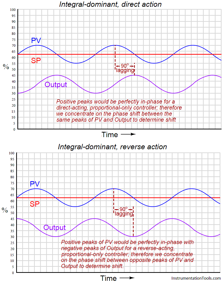
Here, the output waveform is phase-shifted 90 o behind (lagging) the PV waveform compared to what it would be by proportional action alone. This −90 o phase shift is most difficult to see for reverse-acting controllers, since the natural 180 o phase shift caused by reverse action makes the additional −90 o shift look like a +90 o shift (i.e. a −270 o shift).
One method I use for discerning the direction of phase shift for reverse acting controllers is to imagine what the output waveform would look like for a proportional-only controller, and compare to that. Another method is to perform a “thought experiment” looking at the PV waveform, noting the velocity of the controller’s output at points of maximum error (when integral action would be expected to move the output signal fastest).
In the previous example of an integral-dominant reverse-acting controller, we see that the output signal is indeed descending at its most rapid pace when the PV is highest above setpoint (greatest positive error), which is exactly what we would expect reverse-acting integration to do.
Mathematically, this makes sense as well. Integration of a sine function results in a negative cosine waveform:
−cos t = ∫ sin t dt
Another way of stating this is to say integration always adds a −90o phase shift:
sin(t − 90 o) = ∫ sin t dt
If derivative action is set too aggressive for the needs of the process, the resulting output waveform will be phase-shifted +90 o from that of a purely proportional response:
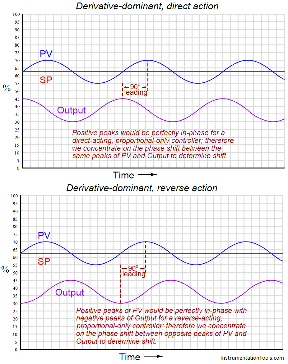
Once again, the direction of phase shift is easiest to discern in the direct-acting case, since we expect the PV and output sine waves to be perfectly in-phase for proportional-dominant response. A +90 o phase shift is very clear to see in the direct-acting example because the peaks of the output waveform clearly precede the corresponding peaks of the PV waveform. The reverse-acting control example is more difficult due to the added 180 o of phase shift intrinsic to reverse action.
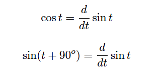
The derivative of a sine function is always a cosine function (or alternatively stated, a sine function with a +90 o phase shift):
You may encounter cases where multiple PID terms are set too aggressively for the needs of the process, in which case the phase shift will be split somewhere between 0 o and ± 90 o owing to the combined actions. In such cases one must “round up” or “round down” the phase shift to the nearest value of −90 o, 0 o, or +90 o in order to determine which of the three actions (I, P, or D, respectively) is most responsible for the oscillations.


Thank you, it is a great article. I was looking for something like this. One question, is this detection method still applicable if the process has a large dead-time like for temperature control ?