Inst ToolsInst ToolsInst Tools
  • Courses
  • Automation
    • PLC
    • Control System
    • Safety System
    • Communication
    • Fire & Gas System
  • Instrumentation
    • Design
    • Pressure
    • Temperature
    • Flow
    • Level
    • Vibration
    • Analyzer
    • Control Valve
    • Switch
    • Calibration
    • Erection & Commissioning
  • Interview
    • Instrumentation
    • Electrical
    • Electronics
    • Practical
  • Q&A
    • Instrumentation
    • Control System
    • Electrical
    • Electronics
    • Analog Electronics
    • Digital Electronics
    • Power Electronics
    • Microprocessor
  • Request
Search
  • Books
  • Software
  • Projects
  • Process
  • Tools
  • Basics
  • Formula
  • Power Plant
  • Root Cause Analysis
  • Electrical Basics
  • Animation
  • Standards
  • 4-20 mA Course
  • Siemens PLC Course
Reading: Raw Counts to Engineering Units : Conversion Formula
Share
Font ResizerAa
Inst ToolsInst Tools
Font ResizerAa
  • Courses
  • Design
  • PLC
  • Interview
  • Control System
Search
  • Courses
  • Automation
    • PLC
    • Control System
    • Safety System
    • Communication
    • Fire & Gas System
  • Instrumentation
    • Design
    • Pressure
    • Temperature
    • Flow
    • Level
    • Vibration
    • Analyzer
    • Control Valve
    • Switch
    • Calibration
    • Erection & Commissioning
  • Interview
    • Instrumentation
    • Electrical
    • Electronics
    • Practical
  • Q&A
    • Instrumentation
    • Control System
    • Electrical
    • Electronics
    • Analog Electronics
    • Digital Electronics
    • Power Electronics
    • Microprocessor
  • Request
Follow US
All rights reserved. Reproduction in whole or in part without written permission is prohibited.
Inst Tools > Blog > Formulas > Raw Counts to Engineering Units : Conversion Formula

Raw Counts to Engineering Units : Conversion Formula

Formula for converting PLC Raw Counts into engineering units or process variable. Check this article how-to convert sensor raw counts in a PLC system.

Last updated: November 3, 2023 2:59 pm
Editorial Staff
Formulas PLC Tutorials
3 Comments
Share
3 Min Read
SHARE

We need to convert sensor raw counts to engineering units in a PLC system.

Contents
Convert Raw Counts to Engineering UnitsFormula

Convert Raw Counts to Engineering Units

Convert Raw Counts to Engineering Units

We have a sensor which gives a raw value input of the range 4000 to 20000. We need the sensor value in a output scaled range of 0 to 1450. Find a formula that will allow to calculate the scaled value from the raw one.

I’ll make up an example: I get a raw reading of 12456 from the sensor. How do we convert that to a scaled output value?

Formula

We have an elevated Zero (4000 = 0 Units) so you need to subtract that from the 12456 to start with. The span of your sensor 0 to 1450 units = 16000 (20000 – 4000).

Once the zero is taken care of it’s a simple percentage or ratio calculation.

((Raw Reading – 4000)/16000) x 1450 = Value

(12456 – 4000) = 8456

8456 / 16000 = 0.5285 i.e your reading is 52.85% of the 1450

0.5285 x 1450 = 766.325 units

another way to visualize it.

0% = 4000
25% = 8000
50% = 12000
75% = 16000
100% = 20000

To go from units to the raw value would be the same except you’d need to add the zero (4000) to the ratio.

What would raw value of 725 units be?

((725/1450) x 16000) + 4000

725/1450 = 0.5
0.5 x 16000 = 8000
8000 + 4000 = 12000

Hopefully now you can solve your raw counts calculations using the above formula.

Spare some time to evaluate your skills on the raw count calculations. Using the above example, find-out scaled output for the following raw counts : 15750, 35780, 6854, 24758. You can share the answers using below comments section.

Do you have any other similar formula for the conversion ? Share with us.

If you liked this article, then please subscribe to our YouTube Channel for PLC and SCADA video tutorials.

You can also follow us on Facebook and Twitter to receive daily updates.

Read Next:

  • Why 4-20mA Standard is so popular?
  • Scaling Sensor Output to Engineering Units
  • Raw Count Calculation for Pressure Transmitter
Don't Miss Our Updates
Be the first to get exclusive content straight to your email.
We promise not to spam you. You can unsubscribe at any time.
Invalid email address
You've successfully subscribed !

Continue Reading

How to Work with Delta PLC Simulator?
Check Block Consistency Tools in Simatic Manager
Conveyor Operation with a Backup Motor using PLC Ladder Diagram
Calculate Control Valve Stem Position
Formulas to calculate mA from PV, LRV and URV
Product Painting PLC Program using Omron CX-Programmer
Share This Article
Facebook Whatsapp Whatsapp LinkedIn Copy Link
Share
3 Comments
  • Krish says:
    December 2, 2018 at 4:53 pm

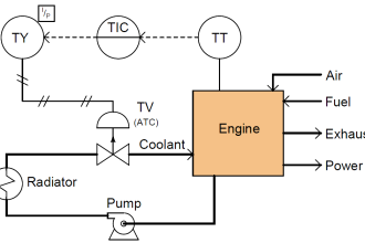
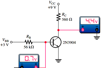
    Here is a typical example where a pressure sensor is used to measure 0-500 PSI and the output is 1-5Vdc.

    First, using the Y=MX+B formula, we determine what each value is in order to calculate for Y.

    X = 4 (since 1-5V has a span of 4 volts. If it was a 0-10Vdc output, X would be 10)

    M = 125 (use divide the Units by the Voltage or Current – 0-500/1-5 = 125) which results in PSI/Volts

    B = -125 ( since the output starts at 1 volt, there is an offset. We calculated a value of 125 PSI/Volt, therefore, 1V = -125) If the output of the sensor was 0-5Vdc, then there would be no offset.

    To test that the values are correct, put them in the equation. 5 volts out should give us 500PSI and 1 volt out should give us 0 PSI.

    Y=125(5) + (-125) = 500PSI
    Y=125(1) + (-125) = 0 PSI

    Reply
    • William says:
      October 1, 2019 at 5:12 pm

      How can I get the disc of plc

      Reply
  • David says:
    May 16, 2019 at 5:22 am

    I would mostly agree with Krish’s approach: the y = mx + b (slope-intercept equation) when properly applied yields reliable results for all linear systems, and works the same way without edge cases for elevated or suppressed zero or span so long as the math and arithmetic are carefully applied to properly represent the situation.

    Students should also learn to solve this equation for other terms, e.g., if y = mx + b, then b = y – mx for any given value of (x,y) in the range of the equation, and x = (y -b)/m for any given value of (x,y) in the range of the equation.

    m, of course is (y2 – y1)/(x2 – x1) for any points (x1, y1) and (x2, y2) in the range of the equation.

    Krish’s approach lacks somewhat in mathematical rigor, though: X is not always equal to 4, because it can take on values in the domain of real numbers from 1 to 5, inclusive.

    When solving for m, the delta-x would be equal to 4 if x1 = 1 and x2 = 5. In this case, delta-y would necessarily be 500 – 0 or 500. m would thus be equal to 500/4 or 125.

    If the order of the (x,y) pairs were reversed, the signs of both delta-x and delta-y would also be reversed and the net result would be the same.

    Reply

Leave a Reply Cancel reply

Your email address will not be published. Required fields are marked *

Stay Connected

128.3kFollowersLike
69.1kFollowersFollow
210kSubscribersSubscribe
38kFollowersFollow

Categories

Explore More

4-20mA Formulas and Examples
4-20mA Graphical Calculations
Structured Text PLC Example for Motor Interlocking and Control
Safety Considerations in PLC System Design
Motor ON OFF Logic in PLC
Light ON OFF Control using PLC
PLC Programming Videos
Things to Take Care of When Designing SCADA System

Keep Learning

OMRON PLC program for waste-burning automation

Waste-Burning System OMRON PLC Program Example

User Defined Function Blocks in PLC

What are User Defined Function Blocks in PLC?

PLC Star-Delta starter with interlock

Schneider PLC Example Program for Star-Delta System

Analog Measurement using Ladder Logic

Analog Measurement using Ladder Logic

Ladder Logic of Motor Forward and Reverse

PLC Programming Example for Motor Forward and Reverse Control

PLC Software Redundancy

Software Redundancy in Siemens PLC – Hardware versus Software

Best 100 PLC Projects for Final Year Engineering Students

Best 100 PLC Projects for Final Year Engineering Students

Schneider PLC Programming Example

Schneider PLC Programming Example for Beginners

Learn More

hydraulic module

Identify all Spool Valve Positions

Instrumentation Diagrams Multiple Choice Questions

Instrumentation Diagrams Multiple Choice Questions

Equal Flow Balance Operation of Parallel Compressors

Types of Surge Control for Parallel Gas Compressors

Temperature Sensor Failure

Temperature Sensor Failure

Ionization Transducers Objective Questions

Ionization Transducers Objective Questions

Kv-value of a valve is determined by a standardised test

Calculate Flow Coefficient Kv of Solenoid Valve

Pressure Gauges with Zero Adjustment

Pressure Gauges Zero Adjustment

Power Systems Questions & Answers

Power Systems MCQ Series 20

Menu

  • About
  • Privacy Policy
  • Copyright

Quick Links

  • Learn PLC
  • Helping Hand
  • Part Time Job

YouTube Subscribe

Follow US
All rights reserved. Reproduction in whole or in part without written permission is prohibited.
Welcome Back!

Sign in to your account

Username or Email Address
Password

Lost your password?