In networking, various types of topologies are used to communicate data between devices. A topology is nothing but how you design an architecture through which the devices can communicate. It can be either star, bus, ring, mesh, tree, etc. (Click here to read more details) One such topology of tree type which is used in very highly advanced networking systems is rapid spanning tree protocol or RSTP. In this post, we will see the concept of rapid spanning tree protocol used in networking systems.
What is Tree Topology?
To all the newcomers who first of all do not know what a tree topology is, let us understand it first. Like a tree which has one single trunk and number of branches and each branch having sub-branches, a tree topology in networking is similar to it. It has a root bridge or switch, which is the central hub or the trunk (root) of the tree. Below this switch, there are multiple child branches or switches which connect to this root hub. Each of these child branches will have it’s own group of sub-branches or switches. So, a switch of one group will communicate to the switch of the other group through it’s parent switch, and then to the root switch. Any problem in a particular group will not affect the other group. This is clearly explained in the link mentioned above in the post.
Rapid Spanning Tree Protocol
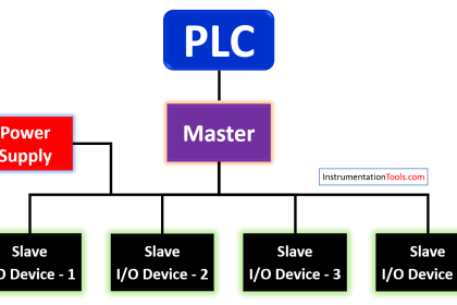
Let us first understand it’s case scenario. Refer to the below image. Extending our concept of tree topology, we find that there is one root switch which is connected to multiple sub-switches. Also, you can see that the sub-switches directly connect with each other, forming a loop. To us, it will look like a very fast and efficient network, but there is a problem with this loop formation. Now, a root switch communicates with other sub-switches by storing and updating the MAC addresses of each device in the network. This is called the MAC address table and helps to identify the actual identity of the device.
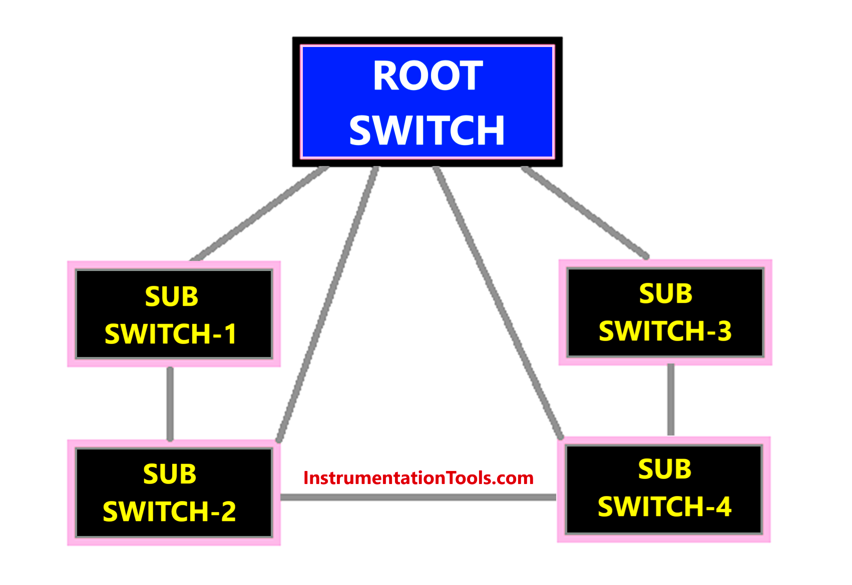
Suppose if switch-1 is broadcasting data in the network. Then, the root switch will receive this message and transmit it to the destination address. But, as the sub-switches are directly connected with each other, switch-2 too will broadcast the same message to the root hub. The root hub now receives two similar messages on the same network. Due to this, confusion will be created in the root hub as it is not able to identify from where the message is received and where to send the address. It will thus send this broadcast message to all the sub-switches. This wastes time, and bandwidth and introduces network latency. In network terms, it is also called a broadcast storm, where switches in the network send out the same messages or duplicate copies, due to the loop cabling done between sub-switches.
This brings into the picture the term RSTP or rapid spanning tree protocol. RSTP is a network topology which prevents network loops and increases network efficiency and reduces downtime. It works the same as a tree structure but avoids network congestion by eliminating loops. Let us see below how RSTP works.
How does the RSTP Protocol work?
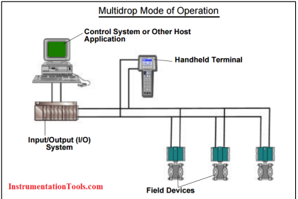
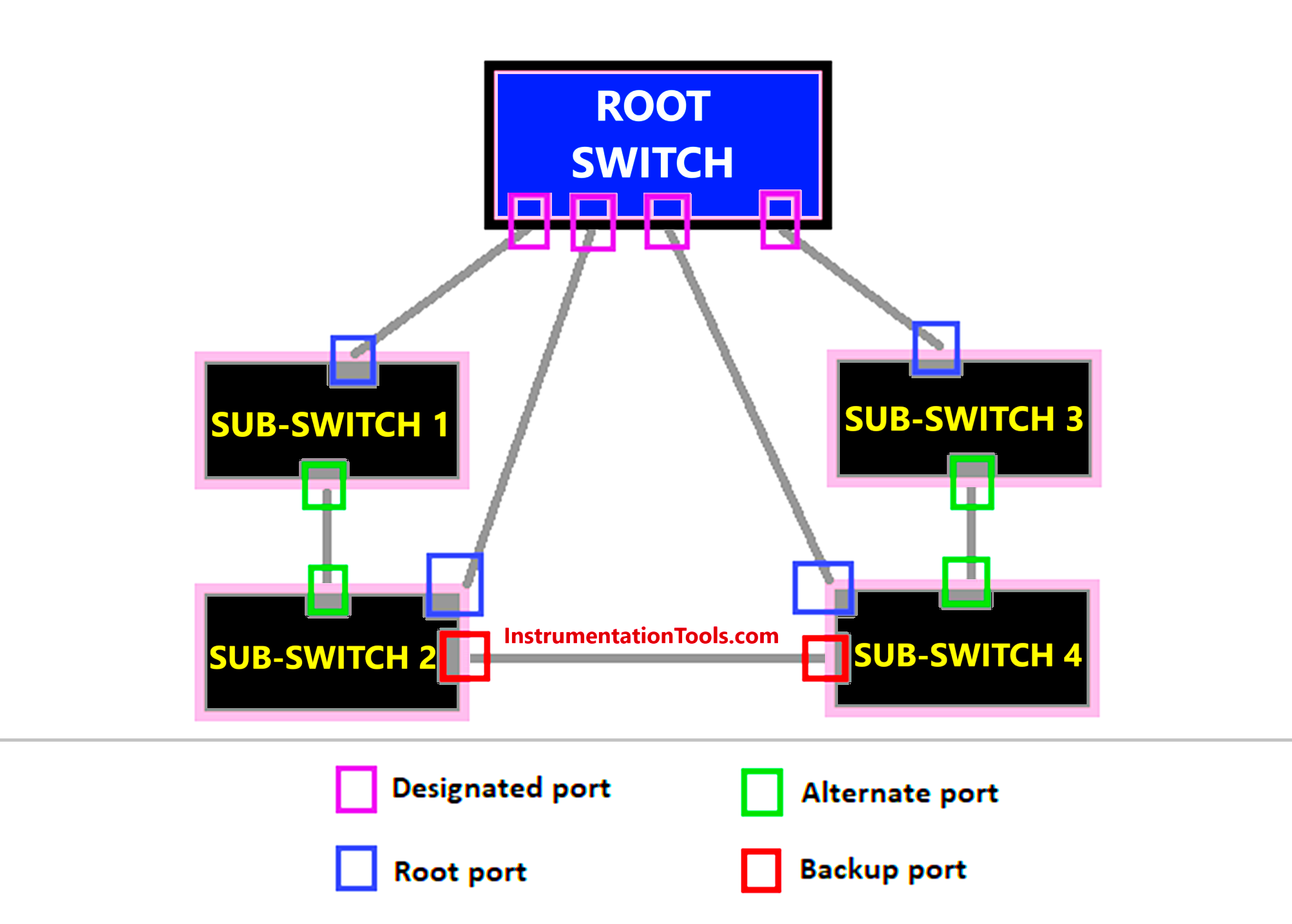
To solve the problem of looping and network congestion, Rapid Spanning Tree Protocol (RSTP) defines the ports in the network as four types – root, designated, alternate, and backup.
Refer to the below image. The root port is the one which is positioned in the sub-switch (the port which is closest to the root switch). It will forward all the messages to the root switch. The designated port is the one which is positioned in the root switch. It will control all the messages received from sub-switches. Alternate ports are positioned in the sub-switches. They work in case of failure of the root port.
Otherwise, it will remain in sleep or shutdown mode, and will not forward any messages. Backup ports function when only the designated port fails, and it will become the master in controlling all the messages. Otherwise, it will remain in sleep or shutdown mode, and will not forward any messages. Due to this system, the looping is not formed in the network, and only forwarding or primary ports work in the system.
The blocked and alternate ports will listen to the messages, but will not respond or forward it. Due to this, the root switch will receive only one type of message. This state is called a discarding state. Before transmitting messages, the root or designated ports will update the MAC addresses in it’s table. This state is called a learning state. Once the roles and MAC addresses have been defined, the root ports will start to forward messages to the destined switches. This state is called a forwarding state.
One thing to remember in the concept of port assignment role is the switch ID. The switch with the lowest ID or lowest MAC ID (in case of a tie) becomes the highest priority switch, or becomes the root switch. Backup and alternate ports forward messages immediately in case of a failure (typically 5 seconds). Due to this, there is no network lag and the efficiency is at it’s best in the RSTP system.
RSTP must be configured in managed switches through it’s separate algorithm settings inside it. The IT engineer must enter the proper values before making the switch work in RSTP. When turned on, RSTP will automatically make all the decisions in deciding the port role and states.
In this way, we saw the concept of rapid spanning tree protocol.
Read Next:
- CANOpen Network Topology
- Network Switch Requirement in SCADA
- Basic Industrial Communication Networks
- Network Topologies Selection Factors
- Network Switch Port Allocation Details