The use of electronics in today’s technology has increased in controlling various actuating systems such as hydraulic and pneumatic systems in process industries and has naturally led to greater in interest in servo and proportional valves.
Both these servo valves and servo proportional valves are electrohydraulic and electro-pneumatic continuously acting type valve that transforms a varying analog or digital input signal into a step less output signal. This signal may be a flow or pressure signal.
These Servo valves and Servo-Proportional Valves are electrohydraulic valves,
These are continuously acting valves that transform a changing analog or digital input signal into a step-less hydraulic output (flow or pressure).
Servo Valves
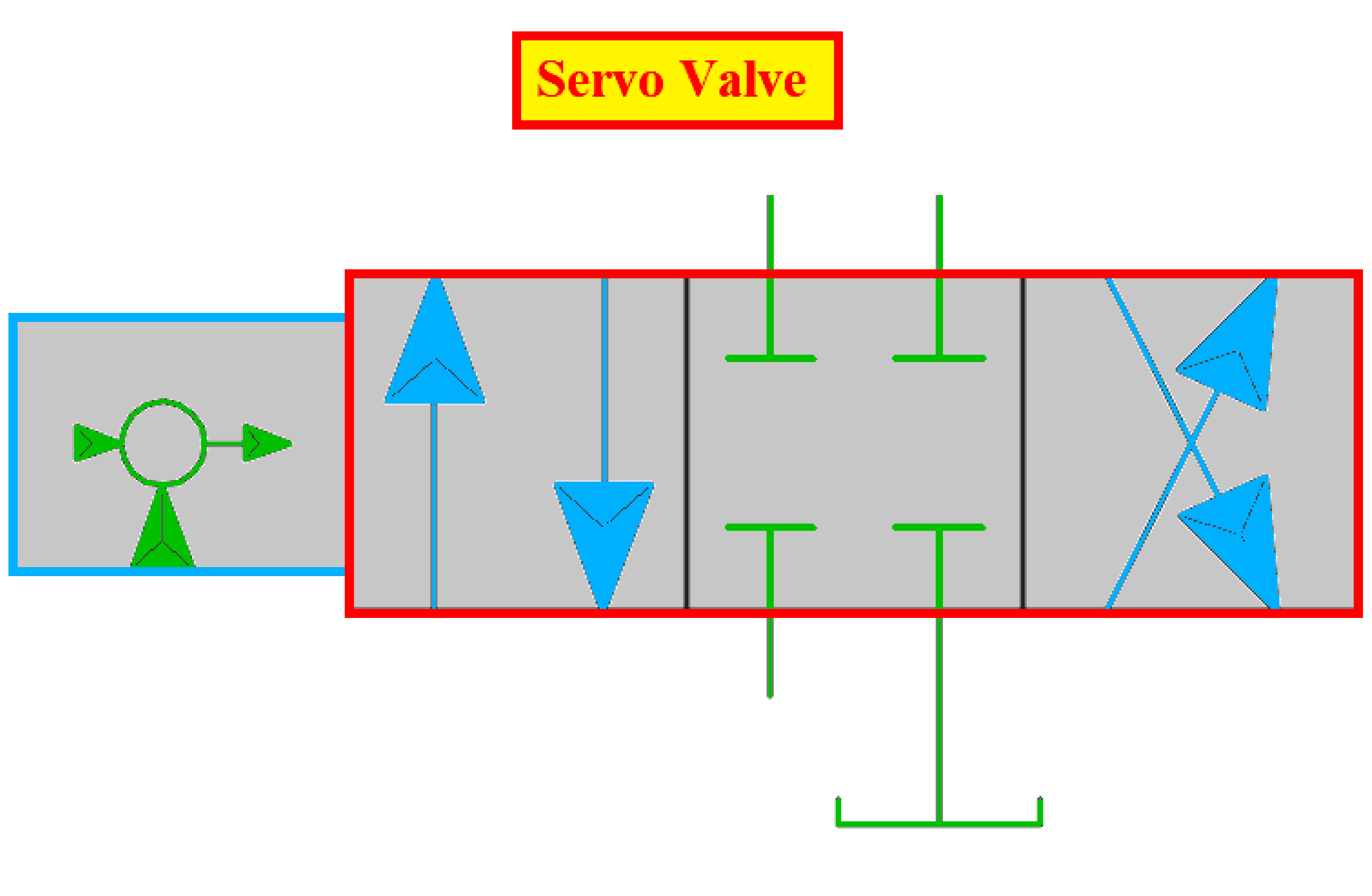
- The term servo valve defines a valve design that consists of a bushing spool assembly Indicated by high-precision metering edges.
- Basically, the name servo valve relates to the term servomechanism, which means that the valve is constantly monitored to control its motion.
- The name proportional describes any action where only one parameter varies in some proportion to another.
- It is a continuously variable, electrically modulated, directional control valve with less than 3% center overlap.
- Servo valves are used in conjunction with closed-loop systems and advanced electronics
- Servo valves function with greater accuracy, very high repeatability, minimum hysteresis, and with a very high-frequency response.
- But servo valves are more expensive.
- A servo valve or pressure control valve is commonly used for controlling the pressure within the circuit through a directional valve in some cases.
- The load cell or pressure transducer senses force or torque
- The servo amplifier analyses the feedback signal from the sensor to control the valve.
- Servo valves are classified as.
- A single-stage servo valve is a directly regulated valve.
- Two valve stages servo valves are comprised of a pilot stage and a final or main stage.
- Three-stage servo valves are similar, except that the pilot itself is a two-stage servo valve.
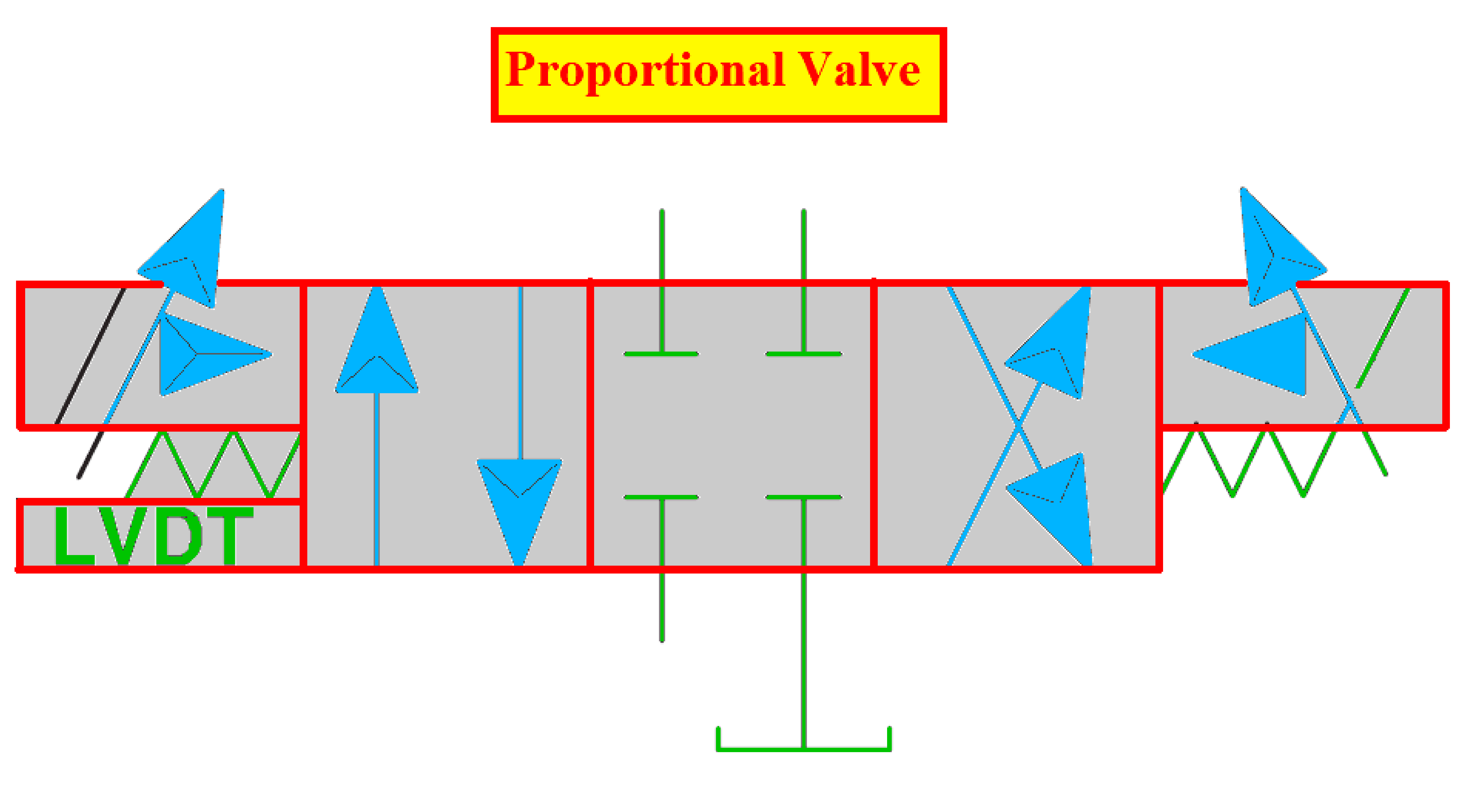
Proportional Valve
- The name proportional valve is used to characterize any kind of action where only one variable varies in some proportion to another variable.
- The term proportional defines a valve with a spool in body design.
- It is a continuously variable, electrically modulated, directional control valve with more than 3% center overlap.
- The function of proportional valves is to produce a smooth and continuous variation in flow or pressure in proportion to an electrical input signal.
- Linking electronics to these valves must be done accurately.
- These valves allow infinite positioning of spools and result in infinite adjustable flow volumes.
- An infinite positioning of the spool can be achieved by using stroke-controlled actuators that use pneumatic cylinders with proportional valves and solenoids for controlling the direction and speed of motion.
- In some cases, servomotors with electric cylinders are used to control the actuation of the stack-controlled solenoid valves
- In the hydraulics industry, the term proportional valve refers to a specific type of valve which is quite distinctive to servo valves.
- The variable positioning of valves allows the designing of spools with metering notches for flow control, speed control as well as directional control within one valve.
- Instead of mounting separate valves for direction and speed control, the other major advantage is that when the circuit claims for more than one speed or maximum speed.
- These various speeds are performed by varying the electrical signal level to distribute the flow or speed as required.
- These valves don’t require any auxiliary components.
- These proportional directional valves are managed or supervised by a DC power supply.
- The proportional controls used with analogous electronic controls will increase the preferable features of acceleration and deceleration.
- This provides a variety of machine cycles, safely operated at higher speeds, with controlled start and stop characteristics.
- Regulated acceleration and deceleration result in enhanced machine cycles and production rates.
- Generally, proportional valves find most of their applications in open-loop conditions
- Where pressure and flow are required to change continuously, where multiple fixed flows and pressure valves can be replaced by a single valve where acceleration and deceleration under control are required.
Differences between Proportional Valves and Servo Valves
| Proportional Valve | Servo valve |
| Open loop control | Close loop control |
| Less costly than servo valves | Very expensive |
| Requires more power about 50W | Requires less power about 0.3W |
| Moderate filtration about 30 micro m | High filtration about 1 to 5 micro m |
| Spools are overlapped | Spools are critically lapped |
| Flow current characteristics are nonlinear | Flow current characteristics are linear |
| Hysteresis is large 0.5% | Hysteresis is low 0.1% |
| Used as flow, pressure & directional control valves | Primarily used in closed loops to create flow and pressure control |
| Used in closed loop control if high performance is not expected | Used in the closed loop if high performance is expected. |
If you liked this article, then please subscribe to our YouTube Channel for Instrumentation, Electrical, PLC, and SCADA video tutorials.
You can also follow us on Facebook and Twitter to receive daily updates.
Read Next:
- What are Oil Burners?
- Ash Handling System
- Steam Ejector Principle
- Boiler Coal Feeding System
- Turbine Troubleshooting Tips