Inst ToolsInst ToolsInst Tools
  • Courses
  • Automation
    • PLC
    • Control System
    • Safety System
    • Communication
    • Fire & Gas System
  • Instrumentation
    • Design
    • Pressure
    • Temperature
    • Flow
    • Level
    • Vibration
    • Analyzer
    • Control Valve
    • Switch
    • Calibration
    • Erection & Commissioning
  • Interview
    • Instrumentation
    • Electrical
    • Electronics
    • Practical
  • Q&A
    • Instrumentation
    • Control System
    • Electrical
    • Electronics
    • Analog Electronics
    • Digital Electronics
    • Power Electronics
    • Microprocessor
  • Request
Search
  • Books
  • Software
  • Projects
  • Process
  • Tools
  • Basics
  • Formula
  • Power Plant
  • Root Cause Analysis
  • Electrical Basics
  • Animation
  • Standards
  • 4-20 mA Course
  • Siemens PLC Course
Reading: Programmable Logic Controller (PLC) Questions and Answers – 3
Share
Font ResizerAa
Inst ToolsInst Tools
Font ResizerAa
  • Courses
  • Design
  • PLC
  • Interview
  • Control System
Search
  • Courses
  • Automation
    • PLC
    • Control System
    • Safety System
    • Communication
    • Fire & Gas System
  • Instrumentation
    • Design
    • Pressure
    • Temperature
    • Flow
    • Level
    • Vibration
    • Analyzer
    • Control Valve
    • Switch
    • Calibration
    • Erection & Commissioning
  • Interview
    • Instrumentation
    • Electrical
    • Electronics
    • Practical
  • Q&A
    • Instrumentation
    • Control System
    • Electrical
    • Electronics
    • Analog Electronics
    • Digital Electronics
    • Power Electronics
    • Microprocessor
  • Request
Follow US
All rights reserved. Reproduction in whole or in part without written permission is prohibited.
Inst Tools > Blog > Practical Questions > Programmable Logic Controller (PLC) Questions and Answers – 3

Programmable Logic Controller (PLC) Questions and Answers – 3

Last updated: June 6, 2018 10:06 am
Editorial Staff
Practical Questions
No Comments
Share
1 Min Read
SHARE

Suppose we have a PLC connected to three process switches as shown in this illustration:

PLC Programming Questions

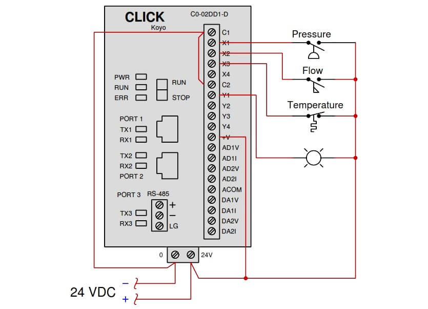
In the above diagram :

  • X1 to X4 : Inputs
  • Y1 to Y4 : Outputs

Determine the switch actuation statuses (i.e. low versus high process stimulus) given the “live” display of the ladder logic program shown here:

Switch ladder logic program

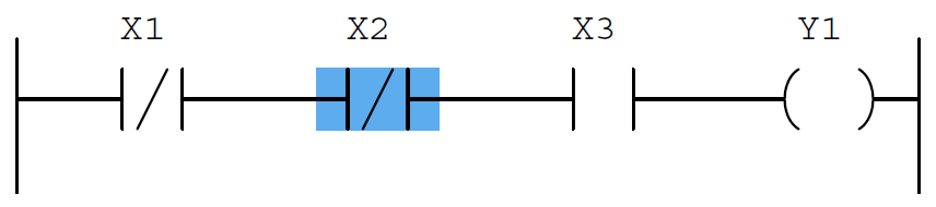
Also, determine the status of the lamp connected to the PLC’s Y1 output.

Answer :

  • High pressure and low flow and high temperature.
  • The lamp will be de-energized.

Share Your Answer / Comments

Credits :  Tony R. Kuphaldt – under CC BY 1.0

For More PLC Questions : CLICK HERE


Don't Miss Our Updates
Be the first to get exclusive content straight to your email.
We promise not to spam you. You can unsubscribe at any time.
Invalid email address
You've successfully subscribed !

Continue Reading

Calculate the Temperature of 4 Wire RTD
Define Normal Status for each of the Process Switch
Solenoid Valves Questions & Answers – 1
A Series of False Pressure Alarms
Programmable Logic Controller (PLC) Questions and Answers – 7
Calculation of Hydrostatic Pressure
Share This Article
Facebook Whatsapp Whatsapp LinkedIn Copy Link
Share
Leave a Comment

Leave a Reply Cancel reply

Your email address will not be published. Required fields are marked *

Stay Connected

128.3kFollowersLike
69.1kFollowersFollow
210kSubscribersSubscribe
38kFollowersFollow

Categories

Explore More

Identify Level Control Loop Tuning Problems
Determine LRV and URV settings for the Level Transmitter
Identify the Pressure Gauge Error
Displacer Level Transmitter Question & Answer
Calculate LRV and URV for 4-20 mA Loop-powered DP Transmitter
Fisher model 546 I/P transducer
Calculate Incident Power in Radar Level Measurement
Loop Powered Pressure Transmitter

Keep Learning

liquid level Measurement

Hydrostatic Level Measurement – Temperature related Density Change Effects

Signal Strength of Guided-wave Radar Level Instrument

Signal Strength of Guided-wave Radar Level Instrument

Calculate the Thermocouple’s Measurement Junction Temperature

Calculate the Thermocouple’s Measurement Junction Temperature

Accuracy of a Manometer

What Affect the Pressure Measurement Accuracy of a Manometer?

DP Transmitter Wet Leg Compensating Impulse Line

Questions on DP Transmitter Wet Leg Compensating Impulse Line

pressure transmitter calibration setup

Questions on Pressure Transmitter Calibration Setup

LRV and URV of PT for Extreme Limits of Empty and Full

LRV and URV of PT for Extreme Limits of Empty and Full

Pitot tube

Pitot Tube Flowmeter Calculations

Learn More

Schematic Diagram

Schematic Diagram

Design Logic Diagrams with Standard Formats for Process Control

Design Logic Diagrams with Standard Formats for Process Control

Components of CCTV System

Free Download CCTV Book

Field Transmitter Range Calculation

Transmitter Turndown Ratio, Set Span and Zero Span

Flame Detector Testing Procedure

Flame Detector Testing Procedure

Pressure instruments example circuit

Motion-Balance and Force-Balance Instruments

PLC Signal Flow

Basic DCS/PLC Signal Flow – Video

Reset Logic for pump Run Hours

PLC Program to Count Running Hours of any Equipment

Menu

  • About
  • Privacy Policy
  • Copyright

Quick Links

  • Learn PLC
  • Helping Hand
  • Part Time Job

YouTube Subscribe

Follow US
All rights reserved. Reproduction in whole or in part without written permission is prohibited.
Welcome Back!

Sign in to your account

Username or Email Address
Password

Lost your password?