Inst ToolsInst ToolsInst Tools
  • Courses
  • Automation
    • PLC
    • Control System
    • Safety System
    • Communication
    • Fire & Gas System
  • Instrumentation
    • Design
    • Pressure
    • Temperature
    • Flow
    • Level
    • Vibration
    • Analyzer
    • Control Valve
    • Switch
    • Calibration
    • Erection & Commissioning
  • Interview
    • Instrumentation
    • Electrical
    • Electronics
    • Practical
  • Q&A
    • Instrumentation
    • Control System
    • Electrical
    • Electronics
    • Analog Electronics
    • Digital Electronics
    • Power Electronics
    • Microprocessor
  • Request
Search
  • Books
  • Software
  • Projects
  • Process
  • Tools
  • Basics
  • Formula
  • Power Plant
  • Root Cause Analysis
  • Electrical Basics
  • Animation
  • Standards
  • 4-20 mA Course
  • Siemens PLC Course
Reading: PLC Switch Actuation Status
Share
Font ResizerAa
Inst ToolsInst Tools
Font ResizerAa
  • Courses
  • Design
  • PLC
  • Interview
  • Control System
Search
  • Courses
  • Automation
    • PLC
    • Control System
    • Safety System
    • Communication
    • Fire & Gas System
  • Instrumentation
    • Design
    • Pressure
    • Temperature
    • Flow
    • Level
    • Vibration
    • Analyzer
    • Control Valve
    • Switch
    • Calibration
    • Erection & Commissioning
  • Interview
    • Instrumentation
    • Electrical
    • Electronics
    • Practical
  • Q&A
    • Instrumentation
    • Control System
    • Electrical
    • Electronics
    • Analog Electronics
    • Digital Electronics
    • Power Electronics
    • Microprocessor
  • Request
Follow US
All rights reserved. Reproduction in whole or in part without written permission is prohibited.
Inst Tools > Blog > Practical Questions > PLC Switch Actuation Status

PLC Switch Actuation Status

Determine the necessary PLC switch actuation status (i.e. low versus high process stimulus) to turn the yellow lamp on.

Last updated: March 11, 2021 11:45 pm
Editorial Staff
Practical Questions
No Comments
Share
1 Min Read
SHARE

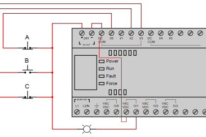
Suppose we have an Allen-Bradley MicroLogix 1000 controller connected to three process switches as shown in this illustration:
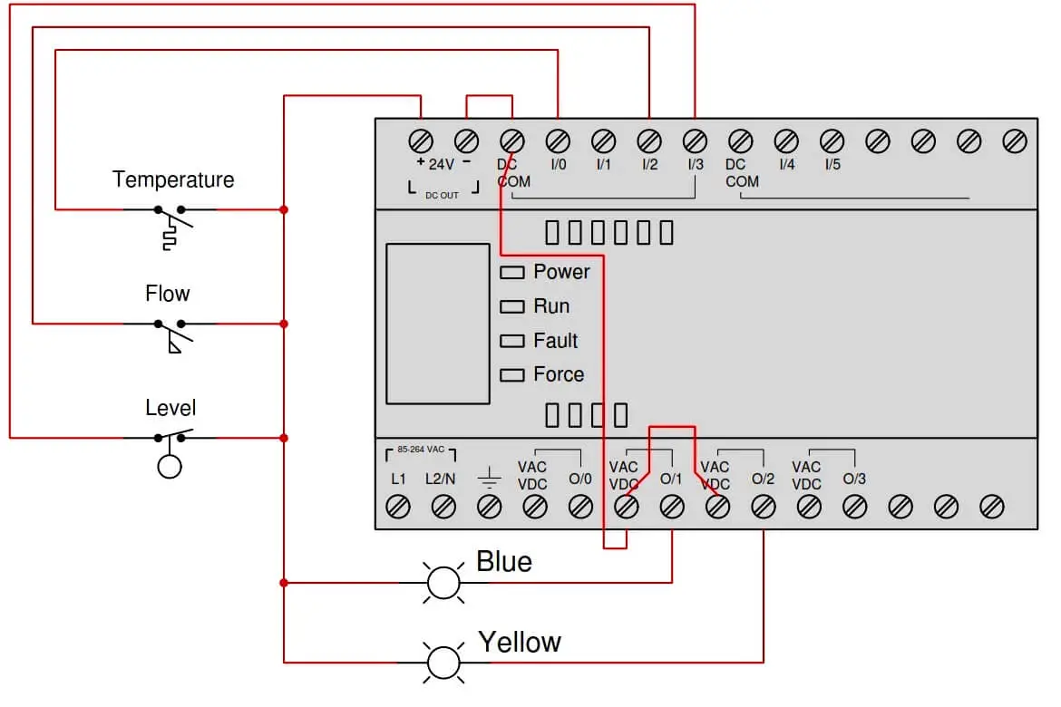
PLC Switch Actuation Status

Determine the necessary switch actuation statuses (i.e. low versus high process stimulus) to turn the blue lamp on, given the following program running in the PLC:
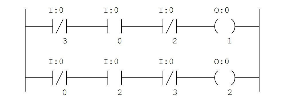
Allen-Bradley MicroLogix 1000 controller ladder logic

Next, determine the necessary switch actuation statuses (i.e. low versus high process stimulus) to turn the yellow lamp on, given the same PLC program.

Answer

High temperature and low flow and high level are required to energize the blue lamp.

Low temperature and high flow and high level are required to energize the yellow lamp.

Share Your Answer / Comments

Credits : by Tony R. Kuphaldt – under CC BY 1.0
Don't Miss Our Updates
Be the first to get exclusive content straight to your email.
We promise not to spam you. You can unsubscribe at any time.
Invalid email address
You've successfully subscribed !

Continue Reading

Solenoid Valves Questions & Answers – 2
Calculate PSV Lift Pressure
Which Tube has most Hydrostatic Pressure?
How Manometer Measures Differential Pressure for Different Fluids?
Stilling Well in Interface Level Measurement System
Why Strain Gauge Resistance Changes as it Stretches and Shrinks?
Share This Article
Facebook Whatsapp Whatsapp LinkedIn Copy Link
Share
Leave a Comment

Leave a Reply Cancel reply

Your email address will not be published. Required fields are marked *

Stay Connected

128.3kFollowersLike
69.1kFollowersFollow
210kSubscribersSubscribe
38kFollowersFollow

Categories

Explore More

Overhead Product Pressure Control Loop
Displacer Level Transmitter Questions
Programmable Logic Controller (PLC) Questions and Answers – 4
pH Transmitter Problem
DP Transmitter Block and Bleed Valves
Why Pressure Vessel Connected to Tubing System?
Pitot Tube Flowmeter Calculations
How to Decrease Span of Pressure Gauge?

Keep Learning

Calculate LRV and URV for 4-20 mA Loop-powered DP Transmitter

Calculate LRV and URV for 4-20 mA Loop-powered DP Transmitter

Calculate voltage across RTD

Resistance Temperature Detector (RTD) Questions – 2

Allen-Bradley MicroLogix PLC Wiring

Programmable Logic Controller (PLC) Questions and Answers – 8

Process Switches Normal Status

Define Normal Status for each of the Process Switch

Programmable Logic Controller (PLC) Questions and Answers

Programmable Logic Controller (PLC) Questions and Answers – 5

Calculation of Hydrostatic Pressure

Calculation of Hydrostatic Pressure

Two pressure switches

Identify Two Pressure Switches Logic

pressure switch ladder-logic diagram

Draw the appropriate Pressure Switch Symbol ?

Learn More

Use of Regions in SCL Language

Use of Regions in SCL Language

Transmitter Proof Testing

Transmitter Proof Testing

Ammonia Analyzer Working

Ammonia Analyzer Principle

PLC Controls a Valve

PLC Controls a Valve Video

Baffle Nozzle Question

Baffle Nozzle Question

PlantPAx Select Add components into Project

How to Import PlantPAx Library?

Converter Instruction in Siemens PLC Programming

Converter Instruction in Siemens PLC Programming

Electrical Resistance Temperature Curves of RTD

Resistance Temperature Detectors (RTD) Construction

Menu

  • About
  • Privacy Policy
  • Copyright

Quick Links

  • Learn PLC
  • Helping Hand
  • Part Time Job

YouTube Subscribe

Follow US
All rights reserved. Reproduction in whole or in part without written permission is prohibited.
Welcome Back!

Sign in to your account

Username or Email Address
Password

Lost your password?