Inst ToolsInst ToolsInst Tools
  • Courses
  • Automation
    • PLC
    • Control System
    • Safety System
    • Communication
    • Fire & Gas System
  • Instrumentation
    • Design
    • Pressure
    • Temperature
    • Flow
    • Level
    • Vibration
    • Analyzer
    • Control Valve
    • Switch
    • Calibration
    • Erection & Commissioning
  • Interview
    • Instrumentation
    • Electrical
    • Electronics
    • Practical
  • Q&A
    • Instrumentation
    • Control System
    • Electrical
    • Electronics
    • Analog Electronics
    • Digital Electronics
    • Power Electronics
    • Microprocessor
  • Request
Search
  • Books
  • Software
  • Projects
  • Process
  • Tools
  • Basics
  • Formula
  • Power Plant
  • Root Cause Analysis
  • Electrical Basics
  • Animation
  • Standards
  • 4-20 mA Course
  • Siemens PLC Course
Reading: Programmable Logic Controller Maintenance Check Points
Share
Font ResizerAa
Inst ToolsInst Tools
Font ResizerAa
  • Courses
  • Design
  • PLC
  • Interview
  • Control System
Search
  • Courses
  • Automation
    • PLC
    • Control System
    • Safety System
    • Communication
    • Fire & Gas System
  • Instrumentation
    • Design
    • Pressure
    • Temperature
    • Flow
    • Level
    • Vibration
    • Analyzer
    • Control Valve
    • Switch
    • Calibration
    • Erection & Commissioning
  • Interview
    • Instrumentation
    • Electrical
    • Electronics
    • Practical
  • Q&A
    • Instrumentation
    • Control System
    • Electrical
    • Electronics
    • Analog Electronics
    • Digital Electronics
    • Power Electronics
    • Microprocessor
  • Request
Follow US
All rights reserved. Reproduction in whole or in part without written permission is prohibited.
Inst Tools > Blog > PLC Tutorials > Programmable Logic Controller Maintenance Check Points

Programmable Logic Controller Maintenance Check Points

Last updated: September 5, 2019 7:41 pm
Editorial Staff
PLC Tutorials
No Comments
Share
5 Min Read
SHARE

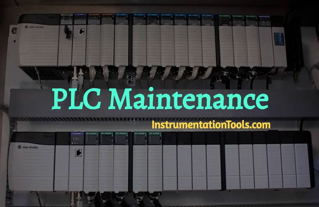
Your schedule Programmable Logic Controller Maintenance will depend on the controller’s environment – the harsher the environment the more frequent maintenance will be needed.

Contents
PLC MaintenanceBackup PLC ProgramCheck LED IndicatorsReplace the BatteryCheck Operating EnvironmentCheck Operating VoltageCheck Program FunctionalityLook For Indications Of Overheated ComponentsClear Dust And Check VentingInspect Battery StatusCheck ConnectionsIdentify Updates NeededRemove Unnecessary ItemsAudit Parts In UseTake Inventory Of Replacement Parts

Setting up a routine maintenance schedule will increase the longevity of your Programmable Logic Controllers (PLCs) and minimize the chance of system malfunction.

PLC Maintenance

PLC Maintenance Check Points

We recommend the following practices at least quarterly to keep your system in good operating condition:

They are as follows –

Backup PLC Program

Save a copy of your PLC program during routine maintenance to ensure a fairly up-to-date backup. In the event a PLC becomes inoperable and has to be replaced, this backup file can be downloaded onto a new PLC.

Check LED Indicators

Check the power and battery LED indicators. If the power LED indicator is off or flickering or if the battery LED indicator is on or flickering this may be a preliminary sign of a low battery or potential power issues.

Replace the Battery

If the Battery OK light is flickering or on, it is time to change the battery. Avoid catastrophic problems if you were to lose main control power by changing the battery regularly.

Check Operating Environment

Check temperature, humidity and other environmental factors to make sure that your PLC is operating within the proper conditions. Also make sure there is good airflow in the cabinet by cleaning filters in the enclosure.

Check Operating Voltage

Check the input voltage that is powering your PLC to make sure that the voltage is within the appropriate range and free from power spikes or ‘brown out’ conditions.

Check Program Functionality

During routine maintenance, check the functionality to make sure the system or equipment that is being controlled is operating as intended.

Look For Indications Of Overheated Components

Check the CPU and modules for distorted, warped, or discolored cases and burnt odors.

Clear Dust And Check Venting

Do not allow dirt and dust to accumulate on the PLC’s components. The central processing unit and I/O system are not designed to be dust proof. Check to be sure none of the PLC and module cooling vents are clogged or blocked by dust or debris.

Make sure that there is sufficient heat dissipation space around the PLC. If heat dissipation is obstructed, circuit malfunction can occur and if conductive dust reaches the electronic boards, it can cause a short circuit, resulting in possible permanent damage to the circuit board.

Inspect Battery Status

Check battery and replace if necessary.

Check Connections

Make sure that all communication cables, plugs, sockets, terminal strips, wiring and modules are connected properly.

If your PLC system is located in an area that experiences constant vibrations that could possible loosen terminal connections, perform this check more often and consider installing a vibration detector.

Identify Updates Needed

Check for any product notices, patches and upgrades and update as necessary.

Remove Unnecessary Items

Keep any items such as drawings, installation manuals or other materials away from the PLC system. Leaving these items on top of the CPU rack or other enclosures can obstruct airflow and create hot spots, ultimately causing a system malfunction.

Audit Parts In Use

Conduct an audit to check each component of your PLC system and determine if parts are good or need replacement.

Take Inventory Of Replacement Parts

Keep a stock of replacement parts on hand to minimize downtime resulting from component failure. Having the right spare in stock during a failure situation can result in shutdown for only minutes instead of hours or days.

Reference : qualitrol
Articles You May Like :

100 PLC Projects List

PLC Math Instructions

PLC Tutorials and Ladder Logics

Multiple Choice Questions of PLC

Programmable Logic Controller Animation

Don't Miss Our Updates
Be the first to get exclusive content straight to your email.
We promise not to spam you. You can unsubscribe at any time.
Invalid email address
You've successfully subscribed !

Continue Reading

Types of Digital Outputs in PLC
Omron PLC Online Training Course
How to use Simulator in Siemens PLC?
Siemens HMI Training – Using UDTs with Faceplates
Introduction to SCADA
#15 PLC Best Practices – Safe State when PLC Restarts
Share This Article
Facebook Whatsapp Whatsapp LinkedIn Copy Link
Share
Leave a Comment

Leave a Reply Cancel reply

Your email address will not be published. Required fields are marked *

Stay Connected

128.3kFollowersLike
69.1kFollowersFollow
210kSubscribersSubscribe
38kFollowersFollow

Categories

Explore More

PLC Conveyor Ladder Logic Program
PLC Compressor Control Ladder Logic
VFD Pros and Cons – Variable Frequency Drives
History of Programmable Logic Controllers (PLC)
How to do Scaling for Analog Input in RSLogix 500?
Check Block Consistency Tools in Simatic Manager
PLC Techniques for I/O Mapping
OPC in Old PLC Systems

Keep Learning

PLC Documents

PLC System Documentation

Retrieve from memory card

How to Retrieve PLC Project From Memory Card?

Siemens PLC Organization Blocks used For Troubleshooting

Tia Portal – OB121 Programming Errors Interrupt Organization Block

PLC Program for Valves

PLC Pump Permissive Interlocks

Repeat Until Statement in SCL Language

Repeat Until Statement in SCL Language

PLC XOR LOGIC with Ladder Diagram

PLC Logic Functions

PLC Program for Positive edge pulse output for one scan cycle

PLC Program for Positive Edge Pulse Output for One Scan Cycle

Normally closed input actuator as stop button.

Normally-Closed Contacts for Stop Buttons

Learn More

Download Free HMI software – CODESYS

Electrical Machines Objective Questions

Electrical Machines MCQ Series 9

Zero Suppression in level Measurement

Zero Suppression and Zero Elevation Calculations

Target Meter Principle

Target Flow Meter – Working Principle, Advantages, Disadvantages

Oracle certification program

Oracle Database 12c Administrator Certified Associate Certification

DP Transmitter Wet Leg Compensating Impulse Line

Questions on DP Transmitter Wet Leg Compensating Impulse Line

baffle-and-nozzle assembly

Pneumatic Sensing Elements

different flow measurement technologies

Different Flow Measurement Technologies

Menu

  • About
  • Privacy Policy
  • Copyright

Quick Links

  • Learn PLC
  • Helping Hand
  • Part Time Job

YouTube Subscribe

Follow US
All rights reserved. Reproduction in whole or in part without written permission is prohibited.
Welcome Back!

Sign in to your account

Username or Email Address
Password

Lost your password?