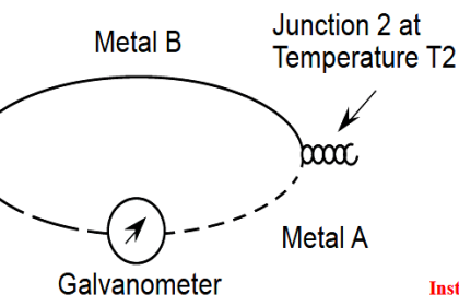
Reference junction compensation is a necessary part of any precision thermocouple circuit, due to the inescapable fact of the reference junction’s existence. When you form a complete circuit of dissimilar metals, you will form both a measurement junction and a reference junction, with those two junctions’ polarities opposed to one another. This is why reference junction compensation – whether it takes the form of a hardware circuit or an algorithm in software – must exist within every precision thermocouple instrument.
Also Read : What is Cold Junction Compensation ?
The presence of reference junction compensation in every precision thermocouple instrument results in an interesting phenomenon: if you directly short-circuit the thermocouple input terminals of such an instrument, it will always register ambient temperature, regardless of the thermocouple type the instrument is built or configured for. This behavior may be illustrated by example, first showing a normal operating temperature measurement system and then with that same system short-circuited. Here we see a temperature indicator receiving a 4-20 mA current signal from a temperature transmitter, which is receiving a millivoltage signal from a type “K” thermocouple sensing a process temperature of 780 degrees Fahrenheit:
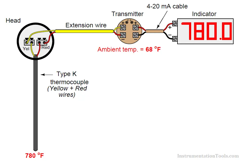
The transmitter’s internal reference junction compensation feature compensates for the ambient temperature of 68 degrees Fahrenheit. If the ambient temperature rises or falls, the compensation will automatically adjust for the change in reference junction potential, such that the output will still register the process (measurement junction) temperature of 780 degrees F. This is what the reference junction compensation is designed to do.
Now, we disconnect the thermocouple from the temperature transmitter and short-circuit the transmitter’s input:
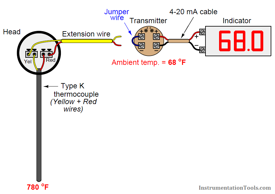
With the input short-circuited, the transmitter “sees” no voltage at all from the thermocouple circuit. There is no measurement junction nor a reference junction to compensate for, just a piece of wire making both input terminals electrically common. This means the reference junction compensation inside the transmitter no longer performs a useful function. However, the transmitter does not “know” it is no longer connected to the thermocouple, so the compensation keeps on working even though it has nothing to compensate for. Recall the voltage equation relating measurement, reference, and compensation voltages in a hardware-compensated thermocouple instrument:
Vmeter = VJ1 − VJ2 + Vrjc
Disconnecting the thermocouple wire and connecting a shorting jumper to the instrument eliminates the VJ1 and VJ2 terms, leaving only the compensation voltage to be read by the meter (Note):
Vmeter = 0 + Vrjc
Vmeter = Vrjc
Note : The effect will be exactly the same for an instrument with software compensation rather than hardware compensation. With software compensation, there is no literal Vrjc voltage source, but the equivalent millivolt value is digitally added to the zero input measured at the thermocouple connection terminals, resulting in the same effect of measuring ambient temperature.
Also Read : Thermocouples Sources of Error
This is why the instrument registers the equivalent temperature created by the reference junction compensation feature: this is the only signal it “sees” with its input short-circuited. This phenomenon is true regardless of which thermocouple type the instrument is configured for, which makes it a convenient “quick test” of instrument function in the field. If a technician short-circuits the input terminals of any thermocouple instrument, it should respond as though it is sensing ambient temperature.
While this interesting trait is a somewhat useful side-effect of reference junction compensation in thermocouple instruments, there are other effects that are not quite so useful. The presence of reference junction compensation becomes quite troublesome, for example, if one tries to simulate a thermocouple using a precision millivoltage source. Simply setting the millivoltage source to the value corresponding to the desired (simulation) temperature given in a thermocouple table will yield an incorrect result for any ambient temperature other than the freezing point of water!
Suppose, for example, a technician wished to simulate a type K thermocouple at 300 degrees Fahrenheit by setting a millivolt source to 6.094 millivolts (the voltage corresponding to 300 oF for type K thermocouples according to the ITS-90 standard). Connecting the millivolt source to the instrument will not result in an instrument response appropriate for 300 degrees F:
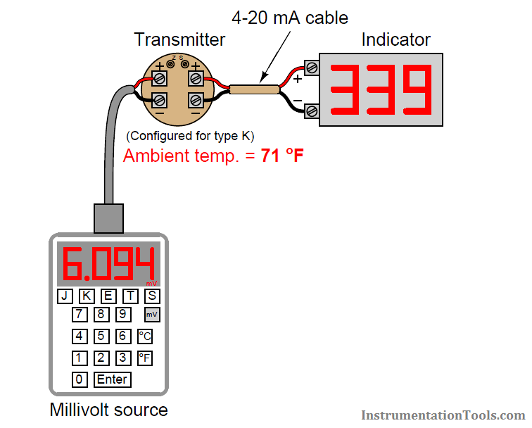
Instead, the instrument registers 339 degrees because its internal reference junction compensation feature is still active, compensating for a reference junction voltage that no longer exists. The millivolt source’s output of 6.094 mV gets added to the compensation voltage (inside the transmitter) of 0.865 mV – the necessary millivolt value to compensate for a type K reference junction at 71 oF – with the result being a larger millivoltage (6.959 mV) interpreted by the transmitter as a temperature of 339 oF.
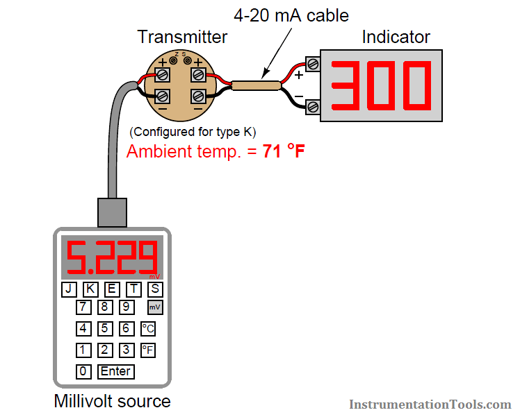
One way to use a millivoltage source to simulate a desired temperature is for the instrument technician to “out-think” the transmitter’s compensation feature by specifying a millivolt signal that is offset by the amount of equivalent voltage generated by the transmitter’s compensation. In other words, instead of setting the millivolt source to a value of 6.094 mV, the technician should set the source to only 5.229 mV so the transmitter’s compensation will add 0.865 mV to this value to arrive at 6.094 mV and properly register as 300 degrees Fahrenheit:
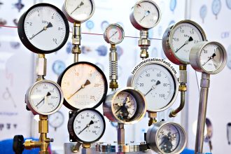
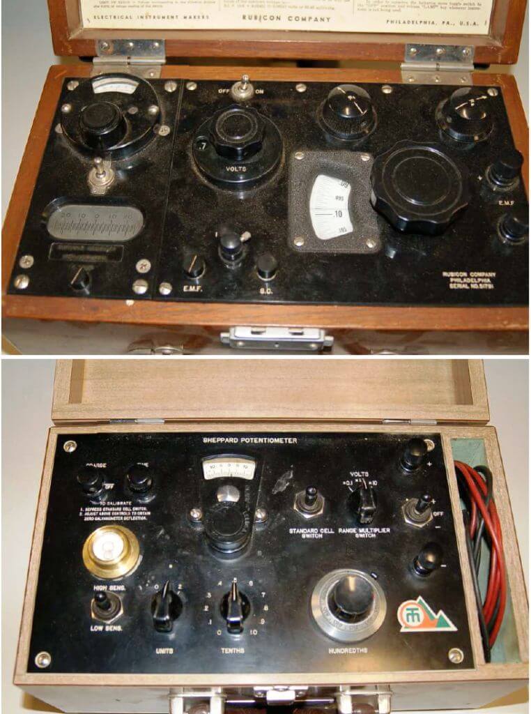
Years ago, the only suitable piece of test equipment available for generating the precise millivoltage signals necessary to calibrate thermocouple instruments was a device called a precision potentiometer. These “potentiometers” used a stable mercury cell battery (sometimes called a standard cell ) as a voltage reference and a potentiometer with a calibrated knob to output lowvoltage signals. Photographs of two vintage precision potentiometers are shown here:
Of course, modern thermocouple calibrators also provide direct entry of temperature and automatic compensation to “un-compensate” the transmitter such that any desired temperature may be easily simulated:
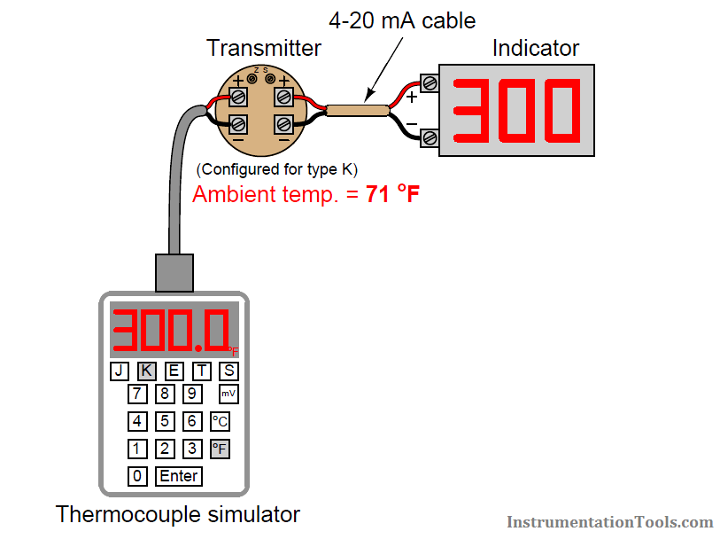
In this example, when the technician sets the calibrator for 300 oF (type K), it measures the ambient temperature and automatically subtracts 0.865 mV from the output signal, so only 5.229 mV is sent to the transmitter terminals instead of the full 6.094 mV. The transmitter’s internal reference junction compensation adds the 0.865 mV offset value (thinking it must compensate for a reference junction that in reality is not there) and “sees” a total signal voltage of 6.094 mV, interpreting this properly as 300 degrees Fahrenheit.
The following photograph shows the display of a modern thermocouple calibration device (a Fluke model 744 documenting process calibrator) being used to generate a thermocouple signal. In this particular example, the thermocouple type is set to type “S” (Platinum-Rhodium/Platinum) at a temperature of 2650 degrees Fahrenheit:
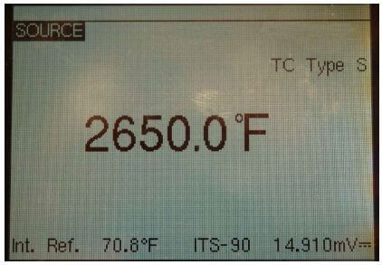
The ITS-90 thermocouple standard declares a millivoltage signal value of 15.032 mV for a type S thermocouple junction at 2650 degrees F (with a reference junction temperature of 32 degrees F). Note how the calibrator does not output 15.032 mV even though the simulated temperature has been set to 2650 degrees F. Instead, it outputs 14.910 mV, which is 0.122 mV less than 15.032 mV. This offset of 0.122 mV corresponds to the calibrator’s local temperature of 70.8 degrees F (according to the ITS-90 standard for type S thermocouples).
When the calibrator’s 14.910 mV signal reaches the thermocouple instrument being calibrated (be it an indicator, transmitter, or even a controller equipped with a type S thermocouple input), the instrument’s own internal reference junction compensation will add 0.122 mV to the received signal of 14.910 mV, “thinking” it needs to compensate for a real reference junction. The result will be a perceived measurement junction signal of 15.032 mV, which is exactly what we want the instrument to “think” it sees if our goal is to simulate connection to a real type S thermocouple at a temperature of 2650 degrees F.
Also Read : RTD or Thermocouple ?
Credits : Tony R. Kuphaldt – Creative Commons Attribution 4.0 License