To understand the PLC working process, let’s take one simple example in figure 1.0. The application is to turn on a lamp using one push-button and stop using another button.
PLC Working Process
Let’s take the IO list before starting the program,
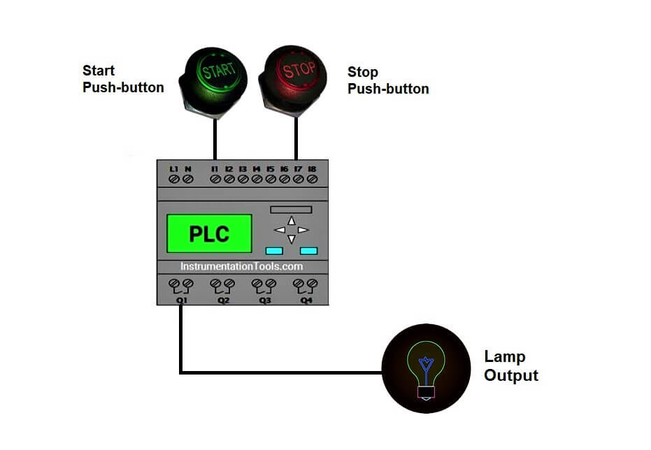
Input components of this application are two buttons, Start and stop pushbuttons. The output component is one lamp. All three IOs in this example come under digital IOs, which meant one bit require for its operation.
Also Read:
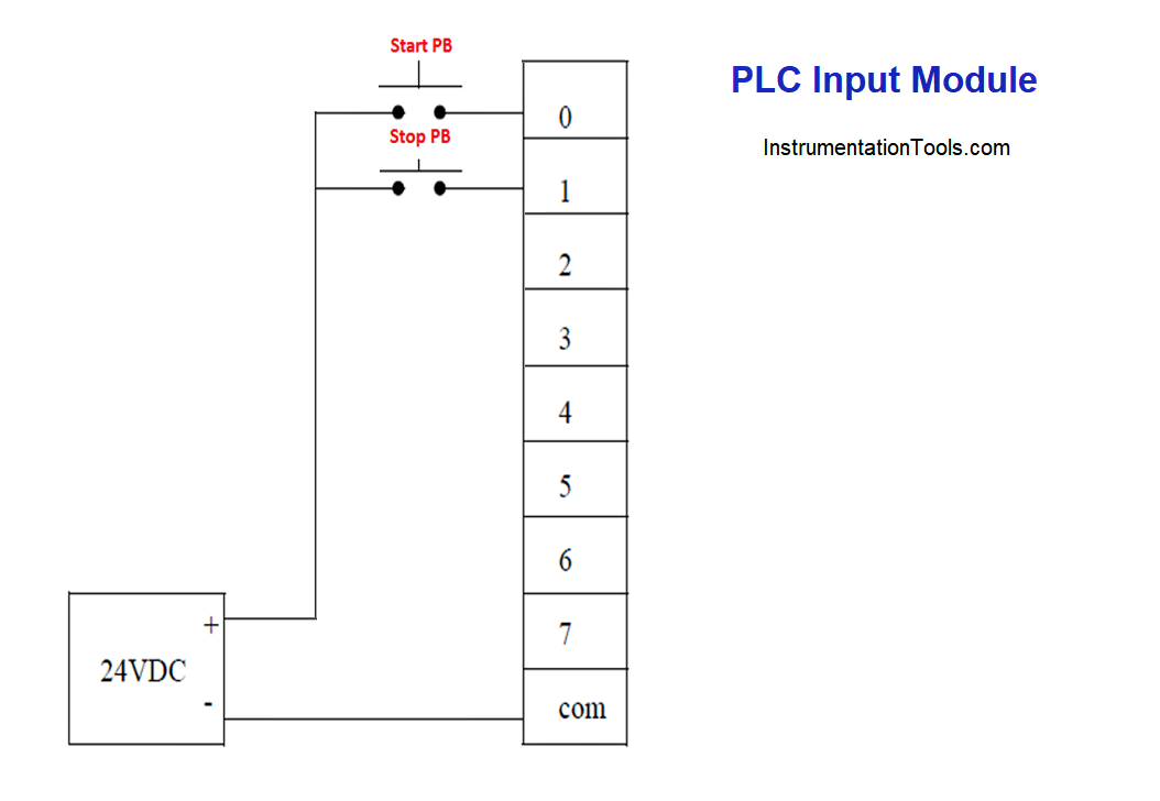
PLC Input Module
Both the inputs are connected to the input module of the PLC and the output lamp is connected to the PLC output module.
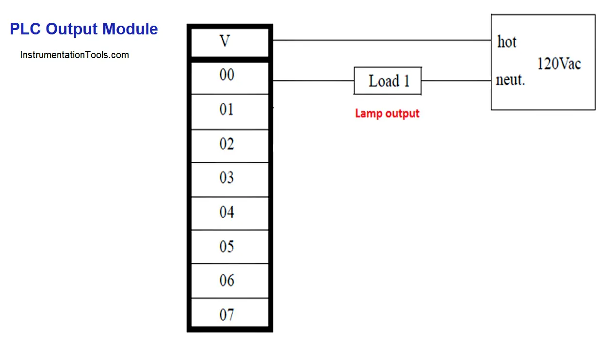
PLC Output Module
Lamp output connected to Out 0 of PLC output module as shown in fig 1.2
According to the PLC vendor, Addressing the PLC IO channels (ports) will get vary. The images above for IO wiring is generalized one. The connection can be sink or source according to the PLC hardware.
Basic PLC Program Example
Let’s write the program for the above example in Allen Bradley PLC Software, refer fig 1.3
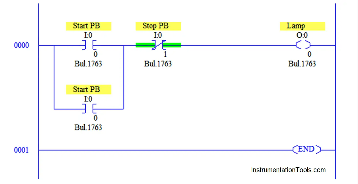
Start push-button (PB) is addressed as I: 0/0 which is the format of giving a single bit address. Stop push-button (PB) as I: 0/1 and output lamp as O: 0/0.
There are two types of contacts in Ladder programming,
- NO (Normally open) and
- NC (Normally closed).
Usually, NO is used to make the contact and NC is to break the contact. In the above example, Start PB is pressed to turn on the lamp (Which is meant to make a contact to turn ON lamp), so we used normally open contact of PB.
The lamp is a coil, which will turn on if PB is pressed. But when using pushbutton (PB) we should clearly understand its working flow. Whenever we press PB, only that time it will make a contact, if release the PB, it will turn off the lamp.
Latching is another concept in the ladder to make a contact continuously. We latched another contact named the same as start PB address in parallel to start PB. Whenever start PB is pressed, it latched this parallel contact to make the lamp on continuously.
Stop PB is to turn off the lamp which is meant to break the contact, NC contact is used in series with Start PB. Whenever it is pressed it will turn off the lamp by breaking the latching circuit.
Push buttons are used in Industries for their easy handling and rust-free properties.
Once the logic is done in PLC programming software, We have to download the program into the PLC controller using PPI (Point to Point Cable) or Ethernet Cable. CPU has to be in the run mode to see the output and input status in software.
CPU of the controller stores the program in its memory. When the corresponding physical input goes high, the CPU reads the input details to the program, performs the logic we have written inside the program, and fetches the output to output modules which will turn on/off the physical output. This reading, processing, and fetching of IOs inside the CPU is called SCAN time.
The same concept can be done by using the relay concept.
Normally open push button will be looks like below, in relay logic
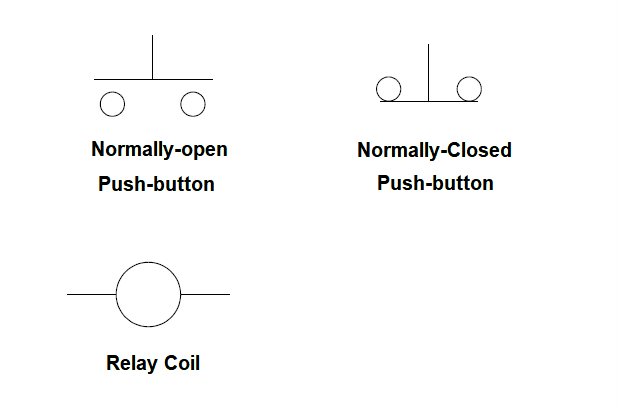
A normally closed push button will be looks like as shown in the above diagram.
The relay coil symbol is also shown in the above diagram.
Replacing the NO and NC contacts with the above symbols can build the relay logic.
If you liked this article, then please subscribe to our YouTube Channel for PLC and SCADA video tutorials.
You can also follow us on Facebook and Twitter to receive daily updates.
Read Next: