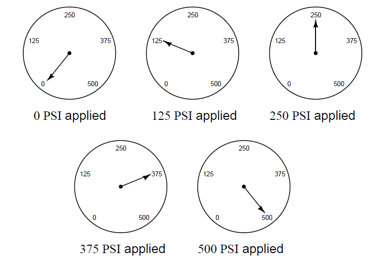
A pressure gauge is supposed to accurately indicate applied pressure over its full calibrated range.
In this example, a gauge with a range of 0 to 500 PSI is subjected to five different pressures along that range, and its response is accurate at all those points:
Describe, by drawing a set of five meter readings such as the set shown above, how a pressure gauge accurate at 0% and 100% of applied pressure – but with a nonlinearity problem between the LRV and URV points – might respond to the same five applied pressures.
Furthermore, describe how a bourdon tube pressure gauge instrument might be adjusted for linearity. In other words, how may a non-linear pressure gauge be calibrated to become more linear?
Here is one example of how a pressure gauge might respond in a non-linear fashion to the same five applied pressures, while still being accurate at the LRV and URV points:
Here, the gauge reads high at the 25% point (125 PSI), slightly low at the 50% point (250 PSI), and low at the 75% point (375 PSI), while still accurate at 0% (0 PSI) and 100% (500 PSI).
Any adjustment that affects the traveling angle of the mechanism will have an effect on linearity.
Some (high-quality) pressure gauge mechanisms are equipped with an adjustable-length link to facilitate changes to this angle:
It is sage advice to leave all angle adjustment(s) untouched until all possible zero and span adjustments have been made to the instrument. Usually, it is possible to get a non-linear instrument to read within specified tolerance in a 5-point calibration just by adjusting the zero and span adjustments.
In many mechanical instruments, a simple linearity alignment is to apply a 50% input signal and check for link/lever perpendicularity (that all links and levers intersect at 90o angles to each other).
Explain how keeping both “As-Found” and “As-Left” calibration records on instruments such as this pressure gauge make it possible to track long-term calibration drift.
Can a non-linearity error be corrected by adjusting the zero and/or span screws on an instrument? Why or why not?
Share your answers with us through below comments section.
Credits: Tony R. Kuphaldt
VFD simulator download: Master the online tool from the Yaskawa V1000 & programming software for…
The conveyor sorting machine is widely used in the packing industries using the PLC program…
Learn the example of flip-flop PLC program for lamps application using the ladder logic to…
In this article, you will learn the STAR DELTA programming using PLC controller to start…
Lube oil consoles of rotary equipment packages in industrial process plants are usually equipped with…
Rotating equipment packages such as pumps, compressors, turbines need the lube oil consoles for their…


