Ina process plant, on/off control is done through the PLC or DCS.
The below Figure is an overview of one discrete/digital (on/off) circuit, showing the entire process from the power supply through the sensor and on to the PLC.
PLC Digital Signals Wiring Techniques

In Above Figure, a level switch is mounted to a vessel. The switch is monitored by a PLC digital input module. The circuit is powered through a circuit breaker (CB2) in an instrument power panel.
The main power feed is brought to a marshalling panel, where the power is split, feeding multiple fused circuits. Fuse 03FU is the main disconnect fuse, while the remaining fuses are distribution fuses. Fuse 06FU feeds our circuit.
Hot (electrically live) wire 06A is passed to the field junction box (FJB) as one wire in a multi-conductor cable. This cable, sometimes called a homerun or main cable, is broken out at the field junction box (FJB), where, in this example, two unshielded twisted pair cables are fed to the end device, LSH-47.
This leaves one spare conductor. The hot wire 06A hits the + terminal of the form- A contact and jumpers to the H terminal to power up the electronics of the level switch.
The wire number changes across the relay contact to 06B. This wire feeds the signal back to the FJB, where the signal is passed back to the termination cabinet via the multi-conductor homerun cable.
There the signal and neutral are paired and passed to the PLC module. Note that the return neutral wire, labeled 02N (since it is the return wire for CB2), is split to the PLC and the level switch.
NOTE: It is always advisable to use twisted-pair wire when connecting to a PLC system. Twisted-pair cables exhibit excellent noise immunity, which is particularly useful when connecting to high-impedance loads, such as those found on PLC/DCS I/O modules.
A high-impedance load can be particularly sensitive to noise since the attendant current is so low, and the amount of actual work being done is minimal.
That is it, in a nutshell. The following is a commentary on connectivity issues related to PLC/DCS signal wiring.
a. Sinking and Sourcing
The terms sinking and sourcing are used to describe the way a particular component in the circuit relates to power flow. These terms actually stem from the days of transistor logic.
A transistor can be thought of as a simple switch for this discussion (Below Figure).

DC (+) is DC Positive Terminal, DCC is DC common
This type of transistor requires a small resistance on its collector (the upper side) for current limiting.
In the Case 1 example,
the resistor is in place, with the load shown in series with the transistor’s emitter. When the transistor conducts, current flows through the resistor, the transistor, and then through the load.
This circuit was not used very much because the current divides across the internal circuitry, leaving less power available to drive the load and driving temperatures up in the I/O module.
Case 2
This provides a more typical sourcing circuit, where the PLC output, by turning off, switches the full-load current to drive the load. When the output turns on, the transistor conducts, causing most of the current to be shunted through it, starving the load, and thereby de-energizing it.
The downside of this configuration is that a small leakage current will continue to be present across the load, as a certain amount of current will continue to be directed across the load, though not enough, typically, to cause the load to stay energized. When troubleshooting, however, a small voltage will be detected across a de-energized load.
In the Case 3 example,
the load is the collector resistor. When the transistor conducts, the load energizes. From the standpoint of the board electronics, this is a better configuration because most of the heat is dissipated by the load.
The downside of this configuration is that “switching the neutral” is counter-intuitive and can be unsafe, as full voltage is present at both the positive and negative terminals of the load when it is de-energized.
For these reasons, Case 2 has evolved to become the most common output configuration. This sinking /sourcing concept can be extended to any circuit.
b. Circuit Protection (Fusing)
Most I/O modules are internally fused. However, that does not mean all that much to the user. While the internal fuse does limit damage to the module itself, in most cases the module still must be sent to the factory to be repaired. So the end result is the same to the user—a broken module.
As a result, it is good practice to add external fuses to each I/O point, with a rating just below the fuse rating on the module circuit board. While this limits the size of the load that can be driven directly by the module, the internal fuse and module are protected.
Caution: If internally fused discrete outputs are embedded in interlock chains, or if they are in circuits that depend on normally closed contacts to initiate safety actions, then another type of module that is unfused should be used.
Or interposing relays could be deployed. It is possible to have the I/O point function normally (e.g., close its contacts, and report to the program that it has closed them) but still not pass power due to a blown internal fuse.
c. Digital Input (DI) Circuits
Digital input (DI) modules continually scan their input points for the presence or absence of voltage. If voltage is present, a 1 is written to a memory location. If voltage is absent, a 0 is written there.
The required voltage type and magnitude are two of the factors that distinguish one DI module from another.
Most DI points have high impedance, thus minimizing the amount of current absorbed, and so have a relatively minor effect on the power distribution system.
Each digital input point can be thought of as a lamp, one that is either on or off. DI modules can be electrically isolated point to point, or they can be grouped by internally bussing the I/O common.
Most modules today are grouped, as grouping allows for higher density. As we have seen, point densities of up to 32 points per module are common in the grouped configuration.
The below Figure shows two different DI modules. The first module internally busses the DC(+) side of the circuit. The I/O point then passes power to the field device.
This type of module is called a sourcing module. This configuration is unusual. Switching the common side in the field is typically not done.

If the module internally busses the DC common side of the circuit, then the module is considered a sinking module.
The I/O point completes the path to DC common. This configuration is used in the vast majority of cases because it allows each I/O point to be individually fused near the power supply before power is distributed to the field device.
In either case, the current flows in the same direction through the field-mounted switch.
d. Digital Output (DO) Circuits
Relay contacts are considered output devices because they force other devices to react when they change state. PLC digital outputs can be thought of as relay contacts.
In many cases, that is just what they are. In others, the switching element may be a solid-state device of some sort. Even in that case, the relay analogy works as long as the designer remembers to consider leakage current.
DO modules switch voltage on and off to cause an external device to change state. These modules are either “isolated” or “non-isolated.” If a module is non-isolated, then it is either sinking or sourcing.
1. Isolated DO Circuits
An isolated DO circuit is one in which the power source can be isolated between I/O points. The source is not internally bussed. The cost is two terminals per point, so it is expensive.

There are three sources of wetted power, with points 1, 2, 4, 5, and 6 being isolated from point 3 and points 7 and 8.
In this example, AC is being fed to Point 3, while DC signals are on the remaining points. Doing this demonstrates the possibilities. In practice, it is a good idea to separate AC and DC signals if at all possible.
2. Non-isolated DO Circuits
As with the DI PLC module, point density is an important feature of DO modules. As can be seen in the isolated module in Figure, isolation comes with a price.
A 16-terminal module has a point density of only eight since two terminals are needed per point. By internally bussing a common, the point density can be improved dramatically.
However, the result is a non-isolated module that places limits on the designer. Power sources must be managed. In most cases this is not a problem since extending PLC I/O power to the field device is feasible.
However, if a field device must source its own signal, then an interposing relay must be added to the circuit to provide isolation.

The above Figure shows two different digital output modules. The first internally busses the DC(+) side of the circuit. The I/O point then provides a path to power, making it a sourcing module.
If the module busses the DC common side of the circuit, as shown in Above Figure, Example 1, then the module is considered a sinking module. The I/O point completes the path to common.
This type of module is rarely used today due to the common-side switching. Example 2 is far more common, as it puts the switching action ahead of the load in terms of current flow.
If you liked this article, then please subscribe to our YouTube Channel for PLC and SCADA video tutorials.
You can also follow us on Facebook and Twitter to receive daily updates.
Read Next:
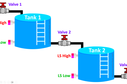
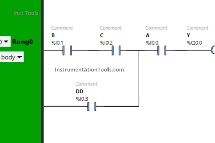
PLC Valve Control Ladder Logic


plc scada is best of the automation system
very valuable information
thanks very much i have a suggestion you can devide this article to 3 part to more easy reading …thanks any way …usefull articles
Thank you very much for valuable information.
Good