Inst ToolsInst ToolsInst Tools
  • Courses
  • Automation
    • PLC
    • Control System
    • Safety System
    • Communication
    • Fire & Gas System
  • Instrumentation
    • Design
    • Pressure
    • Temperature
    • Flow
    • Level
    • Vibration
    • Analyzer
    • Control Valve
    • Switch
    • Calibration
    • Erection & Commissioning
  • Interview
    • Instrumentation
    • Electrical
    • Electronics
    • Practical
  • Q&A
    • Instrumentation
    • Control System
    • Electrical
    • Electronics
    • Analog Electronics
    • Digital Electronics
    • Power Electronics
    • Microprocessor
Search
  • Books
  • Software
  • Projects
  • Process
  • Tools
  • Basics
  • Formula
  • Power Plant
  • Root Cause Analysis
  • Electrical Basics
  • Animation
  • Standards
  • 4-20 mA Course
  • Siemens PLC Course
Reading: PLC Permissive for Motor Control
Share
Notification Show More
Font ResizerAa
Inst ToolsInst Tools
Font ResizerAa
  • Courses
  • Design
  • PLC
  • Interview
  • Control System
Search
  • Courses
  • Automation
    • PLC
    • Control System
    • Safety System
    • Communication
    • Fire & Gas System
  • Instrumentation
    • Design
    • Pressure
    • Temperature
    • Flow
    • Level
    • Vibration
    • Analyzer
    • Control Valve
    • Switch
    • Calibration
    • Erection & Commissioning
  • Interview
    • Instrumentation
    • Electrical
    • Electronics
    • Practical
  • Q&A
    • Instrumentation
    • Control System
    • Electrical
    • Electronics
    • Analog Electronics
    • Digital Electronics
    • Power Electronics
    • Microprocessor
Follow US
All rights reserved. Reproduction in whole or in part without written permission is prohibited.
Inst Tools > Blog > PLC Tutorials > PLC Permissive for Motor Control

PLC Permissive for Motor Control

Last updated: March 4, 2021 3:51 pm
Editorial Staff
PLC Tutorials Practical Questions
2 Comments
Share
2 Min Read
SHARE

A engineer needs to write a PLC program to control a water pump driven by an electric motor. This water pump will be manually started and stopped by pushbutton switches, and shutdown automatically by any one of several “permissive” switches.

The operating statuses of these switches are listed here:
  • Start pushbutton (normally-open): open when unpressed, closed when pressed
  • Stop pushbutton (normally-open): open when unpressed, closed when pressed
  • Low water level (normally-closed): closed when level is low, open when level is adequate
  • Low oil pressure (normally-open): open when pressure is low, closed when pressure is adequate
  • High vibration (normally-closed): closed when still, open when vibrating
  • Water leak detector (normally-open): open when dry, closed when wet (leak detected)

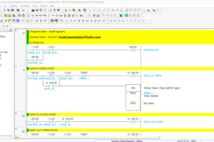
PLC Permissive Motor Control

The engineer’s first attempt is shown here, but it contains a serious error. Identify and correct this error:
PLC program pushbutton switches

Answer :

The Stop_PB contact instruction should be drawn as normally-closed rather than normally-open as shown in the engineer’s first draft of the PLC program.

The program is designed to shutdown the motor when that pushbutton is pressed (i.e. the Stop_PB contact instruction becomes uncolored (i.e. fails to “conduct” virtual power).

We have been told that the real-world Stop pushbutton switch is NO, which means its contact closes when pressed.

This means pressing the Stop pushbutton causes that bit to be 1, which necessitates an NC contact instruction so that it will un-color under that condition.

If you liked this article, then please subscribe to our YouTube Channel for PLC and SCADA video tutorials.

You can also follow us on Facebook and Twitter to receive daily updates.

Read Next:

PLC Counters Program

Contacts and Coils in PLC

PLC Electric Motor Interlocks

Motor Control Circuit

PLC Pump Permissive

Don't Miss Our Updates
Be the first to get exclusive content straight to your email.
We promise not to spam you. You can unsubscribe at any time.
Invalid email address
You've successfully subscribed !

Continue Reading

Schneider PLC Example Program for Star-Delta System
Calculate the Thermocouple Output millivolts
How to Export Data from WinCC Runtime Advanced into Excel using VB Script
How to Detect Speed of Conveyor in PLC?
Connecting Faceplate to PLC Project – HMI Tutorial
Interconnection between PLC, MCC, LCP & Pumps – Video
Share This Article
Facebook Whatsapp Whatsapp LinkedIn Copy Link
Share
2 Comments
  • Bruce says:
    April 19, 2018 at 7:09 am

    Why would you show an example of stop being NO and not fail safe. You would never see it wired this way in an individual setting?

    Reply
  • DIMITRIOS ADAMOS says:
    June 21, 2018 at 8:19 pm

    Hi , i believe that there are two ways that you can program a stop button . this is one way that you mention
    and the other way ,you have stop button NC (hardwired) and you program it as NO in the plc ,fail safe .so there is no wrong in this i believe .great work

    Reply

Leave a Reply Cancel reply

Your email address will not be published. Required fields are marked *

Stay Connected

128.3kFollowersLike
69.1kFollowersFollow
208kSubscribersSubscribe
38kFollowersFollow

Categories

Explore More

Problem with Sump Tank Level Transmitter
Hydrostatic Level Measurement – Temperature related Density Change Effects
Static and Temp Variables in PLC
Current-to-Pressure Transducer Calibration Table
How to Design an Effective HMI? – Human Machine Interface
Two Hand Press Safety Control Circuit
Siemens PLC Mathematics Instructions
Industrial Networking and Wireless Interview Questions

Keep Learning

Sample Schematic Template for Systems Architecture Diagram

Design Document for Project Systems Architecture

Types of Scan Time in a PLC

Programmable Logic Controller (PLC) Scan Time – Types, Theory

Identify which lamp in the following ladder-logic diagram

Identify High Flow Alarm and Low Flow Alarm?

PLC based Drink Dispenser System

PLC based Drink Dispenser System

PLC Program Upload

How to Upload Siemens PLC Programs?

PLC Program for motor operation based on time cycle

PLC Motor Operation based on Time Cycle Sequence – Program

PLC Program for Automatic Oil and Water Separation Process

Oil and Water Separation Process using PLC Programming

Manual sequential logic in Schneider PLC

Programming Schneider PLC Manual Sequential Machine

Learn More

Vortex Flow Meter Animation

Basic Working Principle of Vortex Flowmeter

Common Control Valve Problems

Troubleshooting Common Control Valve Problems

Time Response Analysis

Robotic Control System – Part II

Differential Pressure Transmitter Manifold

Field Instrument Calibration Errors

PLC Program for Trash Compactor

PLC Program for Trash Compactor

Time Response Analysis

Time Response of Second Order Systems – II

Analyzers Questions and Answers

H2S Analyzers Questions & Answers

SCADA Multiple Choice Questions

SCADA Multiple Choice Questions

Follow US
All rights reserved. Reproduction in whole or in part without written permission is prohibited.
Welcome Back!

Sign in to your account

Username or Email Address
Password

Lost your password?