In this article, you will learn the PLC programming example with pushbutton and motor control applications with source code.
Note: The PLC programming example is prepared to learn the basic knowledge of programmable logic controllers. The real-world application will be much more safety-featured with a lot of interlocks, trips, permissive, etc.
PLC Programming Example
Problem Statement:
Design a PLC ladder logic for the following application.
We are using a Push Button to control a Motor.
When the Push Button is pressed and released,
- Motor 1 will be ON after 10 seconds.
- After 10 seconds, Motor 1 goes OFF.
Practical PLC Tutorial Videos
This PLC tutorial video explains the complete programming from the initial step with a detailed explanation for the engineers.
Inputs/Outputs
Digital Inputs:
The required inputs are listed below.
Push Button: I0.0
Digital Outputs:
The required outputs are listed below.
Motor 1: Q0.0
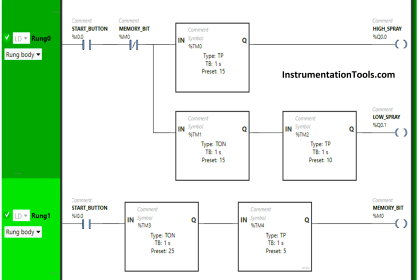
Pushbutton and Motor Logic
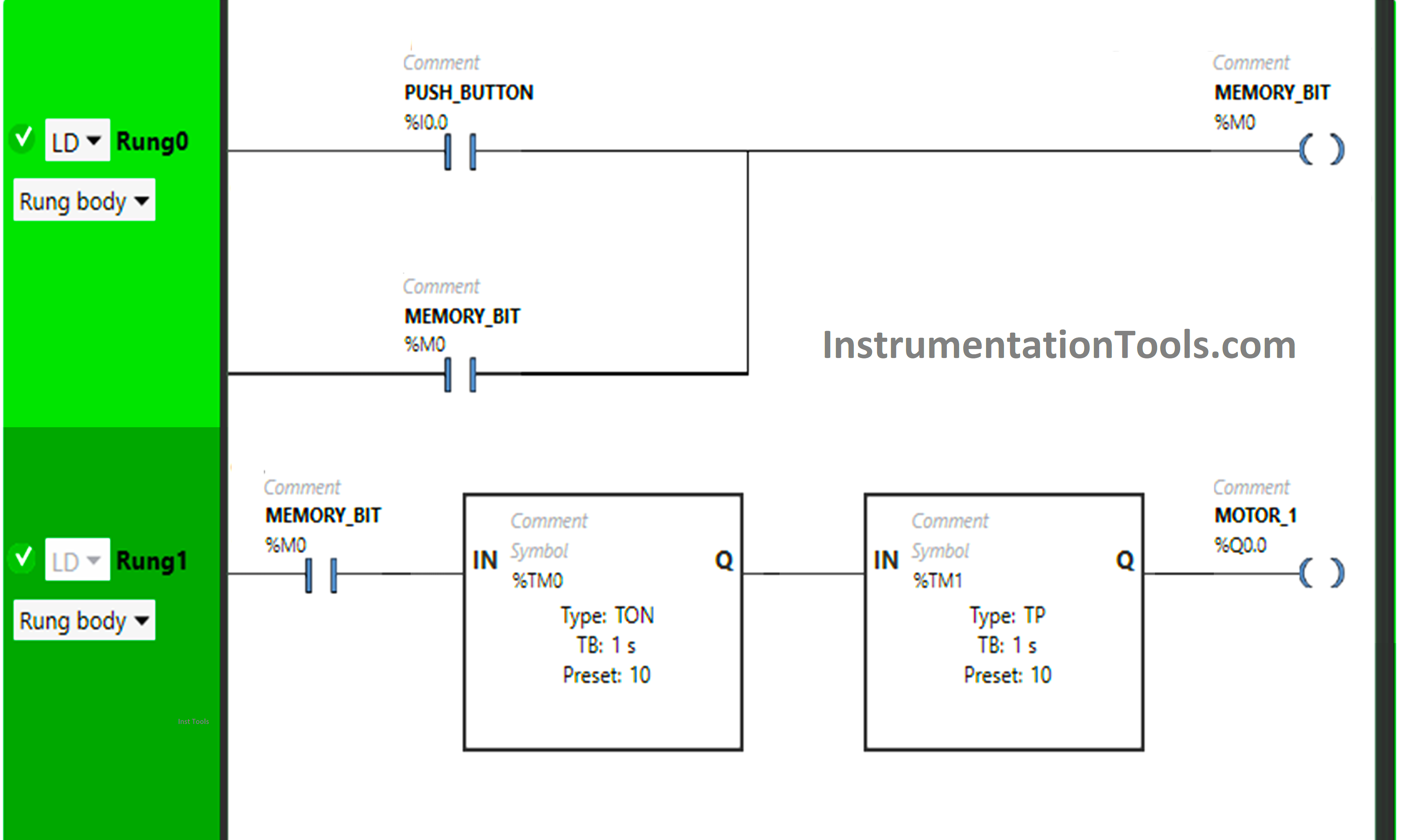
Logic Explanation
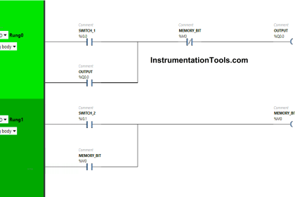
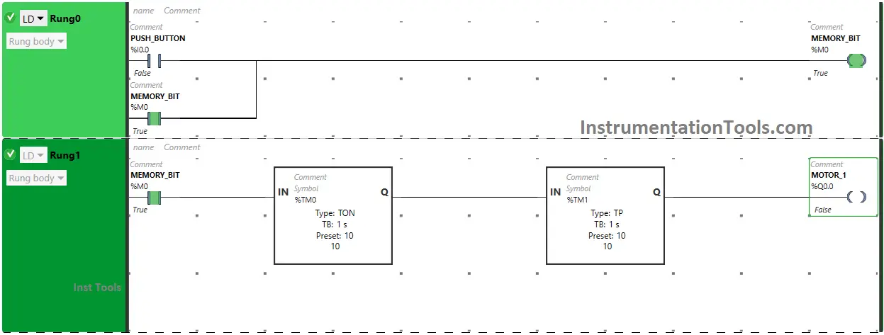
Here we used Normally Open Contact for Push Button and Memory Bit.
Timer Function Block Type TP and Timer Function Block Type TON is used for Motor 1.
In Rung 0:
1) Normally Open Contact is used for Push Button to Turn ON Memory Bit.
2) Latching is used for Memory Bit so that when the Push Button is released, Memory Bit still remains ON.
In Rung 1:
1) Normally Open Contact is used for Memory Bit to Turn ON Motor 1.
2) Timer Function Block type TON is used for Motor 1 to delay the Turning ON.
3) Timer Function Block type TP is used for Motor 1 to delay the turning OFF time.
So, When Push Button is pressed and released, Memory Bit Turns ON in Rung0 and Rung1. When Memory Bit Turns ON in Rung1, Timer starts in Timer Function Block type TON which is set to 10 seconds and then, it delays 10 seconds to Turn ON Motor1.
After 10 seconds Motor 1 Turns ON and when Motor 1 Turns ON, Timer starts in Timer Function Block type TP which is set to 10 seconds and it delays 10 seconds to Turn OFF Motor 1. After 10 seconds, Motor 1 Turns OFF.
Test Case
The PLC program simulated and results shown below.
When Push Button is Pressed and Released
When Push Button is pressed and released, Memory Bit will Turn ON in Rung0 and Rung1.
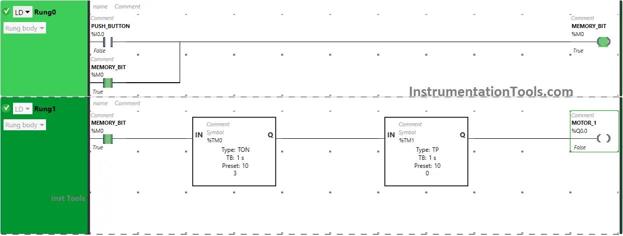
As Memory Bit turns ON in Rung1, Motor 1 will Turn ON after 10 seconds because Timer Function Block type TON is used for Motor 1 which delays the time of Motor 1 to Turn ON.
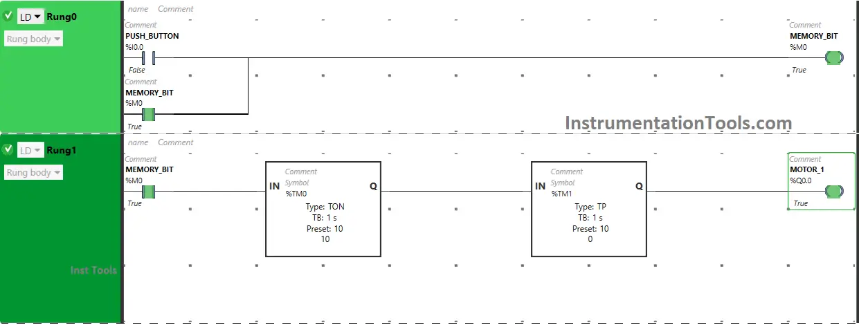
After 10 seconds, Motor 1 will Turn OFF as Timer Function Block type TP is also used for Motor 1 which delays the time of Motor 1 to Turn OFF.
If you liked this article, please subscribe to our YouTube Channel for PLC and SCADA video tutorials.
You can also follow us on Facebook and Twitter to receive daily updates.
Read Next:
- Control PLC Output using Push Buttons
- Boolean Logic to PLC Programming
- PLC Program for Solenoid & Pilot Lamp
- Define Normal Status of a Process Switch
- Normally-Closed Contact for Stop Buttons