Inst ToolsInst ToolsInst Tools
  • Courses
  • Videos
  • Q & A
    • Interview
      • Instrumentation
      • Electronics
      • Electrical
      • Practical Questions
    • MCQ
      • Instrumentation MCQ
      • Electrical MCQ
      • Electronics MCQ
      • Control Systems MCQ
      • Analog Electronics MCQ
      • Digital Electronics MCQ
      • Power Electronics MCQ
      • Microprocessor MCQ
      • Multiple Choice Questions
  • EE
    • Electronics
      • Electronics Q & A
      • Electronic Basics
      • Electronic Devices & Circuits
      • Electronics Animation
      • Digital Electronics
    • Electrical
      • Electrical Basics
      • Electrical Q & A
      • Power Electronics
      • Electrical Machines
      • Electrical Animation
      • Power Systems
      • Switchgear & Protection
      • Transmission & Distribution
  • Measure
    • Control Valves
    • Calibration
    • Temperature
    • Pressure
    • Flow
    • Level
    • Analyzers
    • Switches
    • Vibration
    • Solenoid Valve
  • Control
    • PLC Tutorials
    • Control Systems
    • Safety Instrumented System (SIS)
    • Communication
    • Fire & Gas System
  • More
    • Design
    • Tools
    • Animation
    • Basics
    • Formulas
    • Standards
    • TextBooks
    • Common
    • Software
    • Excel Tools
    • Erection & Commissioning
    • Process Fundamentals
    • Videos
    • Books
Search
All rights reserved. Reproduction in whole or in part without written permission is prohibited.
Reading: 1 to 8 Demultiplexer PLC ladder diagram
Share
Notification Show More
Font ResizerAa
Inst ToolsInst Tools
Font ResizerAa
  • Courses
  • PLC Tutorials
  • Control Systems
Search
  • Courses
  • Videos
  • Q & A
    • Interview
    • MCQ
  • EE
    • Electronics
    • Electrical
  • Measure
    • Control Valves
    • Calibration
    • Temperature
    • Pressure
    • Flow
    • Level
    • Analyzers
    • Switches
    • Vibration
    • Solenoid Valve
  • Control
    • PLC Tutorials
    • Control Systems
    • Safety Instrumented System (SIS)
    • Communication
    • Fire & Gas System
  • More
    • Design
    • Tools
    • Animation
    • Basics
    • Formulas
    • Standards
    • TextBooks
    • Common
    • Software
    • Excel Tools
    • Erection & Commissioning
    • Process Fundamentals
    • Videos
    • Books
Follow US
All rights reserved. Reproduction in whole or in part without written permission is prohibited.
Inst Tools > Blog > PLC Tutorials > 1 to 8 Demultiplexer PLC ladder diagram

1 to 8 Demultiplexer PLC ladder diagram

Implement 1:8 Demultiplexer in PLC using ladder diagram programming language. Learn PLC programming using examples.

Last updated: November 3, 2023 2:02 pm
Editorial Staff
PLC Tutorials
No Comments
Share
4 Min Read
SHARE

This is a PLC Program to implement 1:8 De-multiplexer.

Contents
1 to 8 Demultiplexer PLCProblem DiagramProblem Solution1:8 DeMultiplexer Truth TableList of inputs/outputsList of inputsList of outputsLadder diagram for 1:8 DemultiplexerProgram DescriptionNetwork 1:Network 2:Network 3:Network 4:Network 5:Network 6:Network 7:Network 8:

1 to 8 Demultiplexer PLC

Problem Description

Implement 1:8 Demultiplexer in PLC using ladder diagram programming language.

Problem Diagram
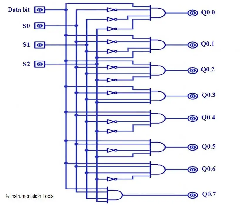
PLC Ladder Logic for Demultiplexer

Problem Solution

Demultiplexer has one data input Di and three select inputs S0, S1 and S3 and 8 outputs Q0.0 to Q0.7.

To select “n” outputs, we need m select lines such that 2^m = n. Depending on the output. The selection of one of the n outputs is done by the select pins.

Realize the de-multiplexer using Logic Gates. Here we will configure de-multiplexer using ladder language.

When three switches are OFF and Di input is pressed then first output will be ON.As per table we can activate output by switching combination.

1:8 DeMultiplexer Truth Table
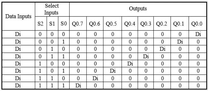
DeMultiplexer PLC Truth Table

List of inputs/outputs

List of inputs

  • S0 :- I0.0
  • S1 :- I0.1
  • S3 :- I1.0

List of outputs

  • Output1 :- Q0.0
  • Output 2 :- Q0.1
  • Output 3 :- Q0.2
  • Output 4 :- Q0.3
  • Output 5 :- Q0.4
  • Output 6 :- Q0.5
  • Output 7 :- Q0.6
  • Output 8 :- Q0.7

Ladder diagram for 1:8 Demultiplexer

PLC Ladder Logic for Demultiplexer - 1
Demultiplexer PLC Ladder
Demultiplexer PLC Ladder Diagram
Demultiplexer PLC Logic
PLC Demultiplexer Logic
PLC Demultiplexer Example
PLC Demultiplexer
PLC Demultiplexer 1 to 8

Program Description

For this application, we used S7-1200 PLC and TIA portal software for programming.

Network 1:

If Data bit (I2.0) is ON and all inputs are OFF (I0.0=0, I0.1=0 and I0.2=0), Output 1 (Q0.0) will be ON.

Network 2:

If data bit (I2.0) is ON, input 1 (I0.0) OFF, input 2 (I0.1) OFF and input 3 (I0.2) is ON, Output 2 (Q0.1) will be ON.

Network 3:

If data bit (I2.0) is ON, input 1 (I0.0) OFF, input 3 (I0.2) OFF and input 2 (I0.1) is ON, Output 3 (Q0.2) will be ON.

Network 4:

If data bit (I2.0) is ON, input 2 (I0.1) ON, input 3 (I0.2) ON and input 1 (I0.0) is OFF, Output 4 (Q0.3) will be ON.

Network 5:

If input 2 (I0.1) and input 3 (I0.2) are OFF and input 1 (I0.0) is ON, Output 5 (Q0.4) will be ON.

Network 6:

If data bit (I2.0) is ON, input 1 (I0.0), input 3 (I0.2) ON and input 2 (I0.1) is OFF, Output 6 (Q0.5) will be ON.

Network 7:

If data bit (I2.0) is ON, input 1 (I0.0), input 2 (I0.1) ON and input 3 (I0.2) is OFF, Output 7 (Q0.6) will be ON.

Network 8:

If data bit (I2.0) is ON, input 1 (I0.0), input 2 (I0.1) and input 3 (I0.2) ON, Output 8 (Q0.7) will be ON.

Note :- Above application may be different from actual application. This example is only for explanation purpose only. We can implement this logic in other PLC also. This is the simple concept of 1:8 Demultiplexer, we can use this concept in other examples also.

All parameters considered in example are for explanation purpose only, parameters may be different in actual applications. Also all interlocks are not considered in the application.

Author: Bhavesh

If you liked this article, then please subscribe to our YouTube Channel for PLC and SCADA video tutorials.

You can also follow us on Facebook and Twitter to receive daily updates.

Read Next:

  • PLC 3 to 8 Line Decoder
  • Matrix Keypad works ?
  • PLC T Flip Flop Logic
  • Flow Totalizer in PLC
  • SR Flip Flop using PLC
Don't Miss Our Updates
Be the first to get exclusive content straight to your email.
We promise not to spam you. You can unsubscribe at any time.
Invalid email address
You've successfully subscribed !

Recommended Articles

What is a Relay? Types of Industrial Relays
PLC Raw Count Calculation for Pressure Transmitter
PLC Math instructions
Function Block (FB) for Motor Control Logic
Product Painting PLC Program using Omron CX-Programmer
How to Operate a Group of Induction Motors using PLC Logic?
Share This Article
Facebook Whatsapp Whatsapp LinkedIn Copy Link
Share
Leave a Comment

Leave a Reply Cancel reply

Your email address will not be published. Required fields are marked *

Stay Connected

128.3kFollowersLike
69.1kFollowersFollow
208kSubscribersSubscribe
38kFollowersFollow

Categories

Recent Comments

  • William Snyder on Top Non-PLC Certification Courses for Automation Professionals
  • Kamli on Top Free PLC Software
  • Guifty Shimica on Top Non-PLC Certification Courses for Automation Professionals
  • Guifty Shimica on Top Non-PLC Certification Courses for Automation Professionals

Explore More

Ladder Logic MCQ Questions and Answers
Start Stop of one Motor from the same Push button PLC program
Pump and Mixer Operations Example: PLC Timer-Based Control
What is the DDE Protocol?
How to Run Multiple Motors with a Single VFD?
PLC based Drink Dispenser System

Related Articles

PLC Program for Automatic Bottle Rejection System

PLC Program for Automatic Bottle Rejection System

PLC Data comparison instructions

PLC Data Comparison Instructions

Studio 5000 Logix Emulate Controller

How to Create New Project in Studio 5000?

How to do Force in GE PLC Proficy Machine Edition?

PLC Ladder Logic Simulator Mobile Apps For Android

PLC Ladder Logic Simulator Mobile Apps For Android

What is a Network Switch?

Network Switch Requirement in SCADA and DCS Architecture

Tanks Draining Control in PLC using Functional Block Diagram

Tanks Draining Control in PLC using Functional Block Diagram

Communication between Intouch Scada and Allen Bradley PLC

Communication between InTouch Scada and Allen Bradley PLC

More Articles

Comparison of Accuracy and Precision

Difference between Accuracy and Precision

Automatic Motor Forward and Reverse Control using Timer

Automatic Motor Forward and Reverse Control using Timer

Why counter-current heat exchangers are better than co-currents?

Why Counter-current Heat Exchangers are better than Co-current?

PLC Program for Tank Heating Control using Heater

PLC Programming for Tank Heating Control using Heater

Common Mistakes in Dead Weight Tester

Common Mistakes to Avoid When Using Dead Weight Tester

O Ring Failure

How O-Ring Failure caused NASA’s shuttle to Blast ?

Metering components to measure flow of Natural gas

Is it Easy to Measure Natural Gas Flow and Volume?

Strainer Principle

Backwashing

Follow US
All rights reserved. Reproduction in whole or in part without written permission is prohibited.
Welcome Back!

Sign in to your account

Username or Email Address
Password

Lost your password?