We need to control the level of tanks which are connected in series. Implement program for Series Tanks Level Control using PLC Ladder Programming.
Series Tanks Level Control
Two tanks are connected in series connection. We need to control of both tanks which are connected in series.
Implement the PLC program for this application.
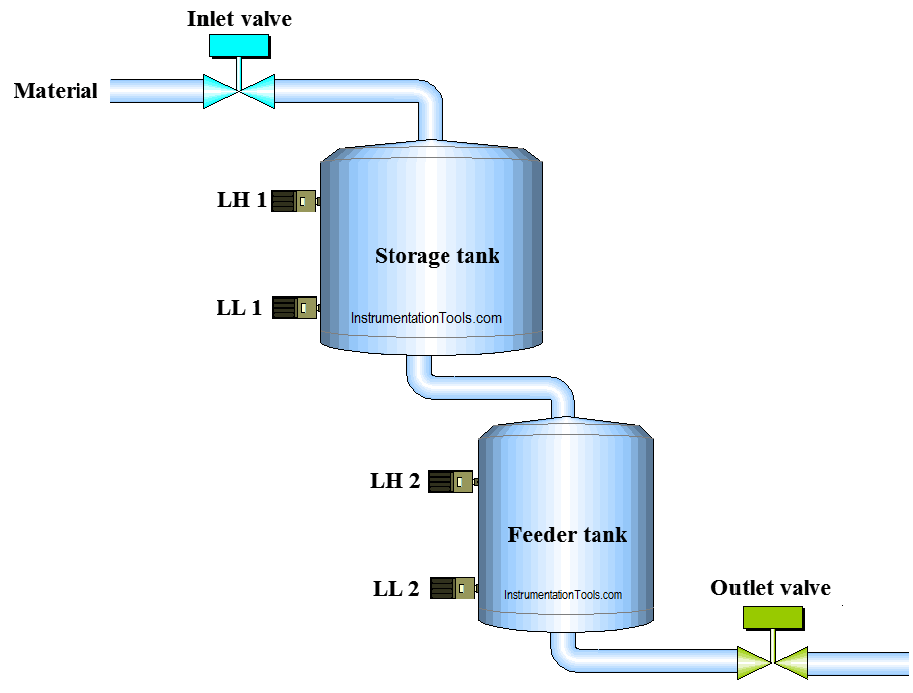
Problem Diagram
Problem Solution
In chemical companies, there are lots of materials which are used for process and also stored in storage tanks for different processes.
Here we consider two tanks, 1. Storage Tank and 2. Feeder Tank.
Storage tank has more capacity than feeder tank. Storage tank is for material storage and feeder tank is for material supply for other process.
Two level switches are used for level detection and one inlet valve for material feeding control.
Consider one manual outlet valve and it can be operated as per requirement by the operator.
For this application we can use PLC, we will write PLC program for this application.
List of Inputs and Outputs
Digital Inputs
- Cycle START :- I0.0
- Cycle STOP :- I0.1
- Low level storage tank (LL1) :- I0.3
- Low level feeder tank (LL2) :- I0.4
- High level storage tank (LH1) :- I0.5
- High level feeder tank (LH2) :- I0.6
Digital Output
- Inlet valve :- Q0.0
M memory
- Cycle ON bit :- M0.0
- Inlet valve close condition :- M0.1
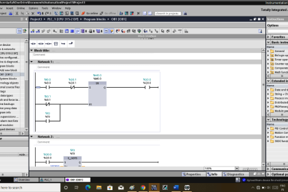
PLC Ladder Diagram for Level control of Series Tanks
Program Description
For this application we used S7-300 PLC and TIA portal software for programming. We can implement this logic by using other PLC also.
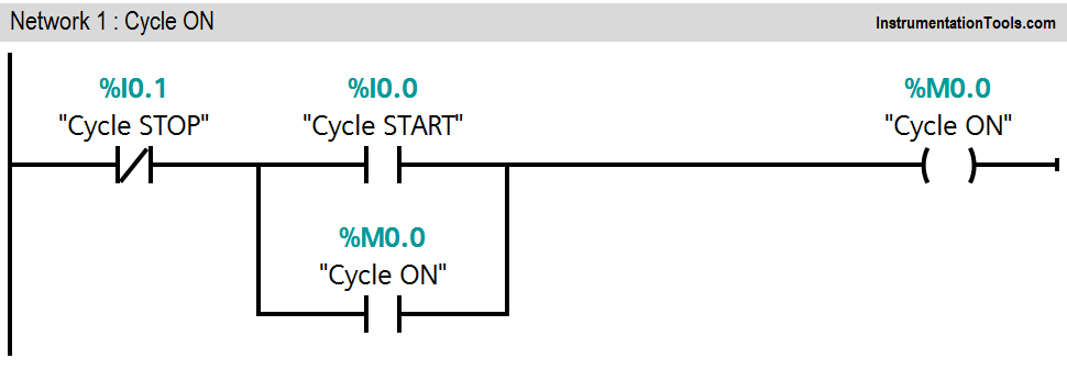
Network 1:
Network 1 is for latching circuit. Whenever START button is pressed (I0.0), Cycle ON (M0.0) bit will be ON. Cycle can be STOP by pressing STOP PB (I0.1).
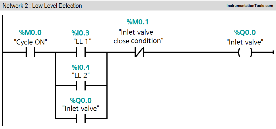
Network 2:
If low level of storage tank (I0.3) or low level of feeder tank (I0.4) is detected, inlet valve (Q0.0) will be ON. (Inlet valve close condition should not present).
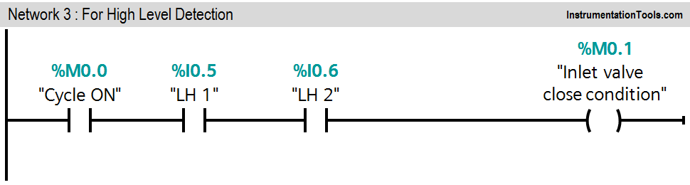
Network 3:
High levels (I0.5 &I0.6) of both tanks are detected, inlet valve close condition will be activated and it will close the inlet valve (Q0.0). Here outlet valve is manual valve, it can be operated by operator as per requirement.
Note :- Above application may be different from actual application. This example is only for explanation purpose only. We can implement this logic in other PLC also.
Result

If you liked this article, then please subscribe to our YouTube Channel for PLC and SCADA video tutorials.
You can also follow us on Facebook and Twitter to receive daily updates.
Read Next:
- PLC Controls a Motor?
- Three Element Drum Level Control
- Water Level Monitoring System
- Latching and unlatching Circuit
- PLC Memory Mapping