Inst ToolsInst ToolsInst Tools
  • Courses
  • Automation
    • PLC
    • Control System
    • Safety System
    • Communication
    • Fire & Gas System
  • Instrumentation
    • Design
    • Pressure
    • Temperature
    • Flow
    • Level
    • Vibration
    • Analyzer
    • Control Valve
    • Switch
    • Calibration
    • Erection & Commissioning
  • Interview
    • Instrumentation
    • Electrical
    • Electronics
    • Practical
  • Q&A
    • Instrumentation
    • Control System
    • Electrical
    • Electronics
    • Analog Electronics
    • Digital Electronics
    • Power Electronics
    • Microprocessor
  • Request
Search
  • Books
  • Software
  • Projects
  • Process
  • Tools
  • Basics
  • Formula
  • Power Plant
  • Root Cause Analysis
  • Electrical Basics
  • Animation
  • Standards
  • 4-20 mA Course
  • Siemens PLC Course
Reading: PLC Program for Latching and unlatching Circuit
Share
Font ResizerAa
Inst ToolsInst Tools
Font ResizerAa
  • Courses
  • Design
  • PLC
  • Interview
  • Control System
Search
  • Courses
  • Automation
    • PLC
    • Control System
    • Safety System
    • Communication
    • Fire & Gas System
  • Instrumentation
    • Design
    • Pressure
    • Temperature
    • Flow
    • Level
    • Vibration
    • Analyzer
    • Control Valve
    • Switch
    • Calibration
    • Erection & Commissioning
  • Interview
    • Instrumentation
    • Electrical
    • Electronics
    • Practical
  • Q&A
    • Instrumentation
    • Control System
    • Electrical
    • Electronics
    • Analog Electronics
    • Digital Electronics
    • Power Electronics
    • Microprocessor
  • Request
Follow US
All rights reserved. Reproduction in whole or in part without written permission is prohibited.
Inst Tools > Blog > Guest Articles > PLC Program for Latching and unlatching Circuit

PLC Program for Latching and unlatching Circuit

Create a PLC Logic for Latching and unlatching Circuit. Find more PLC Tutorials, PLC Programming, PLC example programs, PLC tutorials for beginners.

Last updated: November 3, 2023 10:01 am
Editorial Staff
Guest Articles PLC Tutorials
3 Comments
Share
4 Min Read
SHARE

This is a PLC Program for Latching and an unlatched circuit for output.

Contents
PLC Latching and unlatching CircuitProblem DiagramProblem SolutionPLC Inputs ListPLC Outputs ListPLC Ladder diagram for Latching and unlatched circuitProgram DescriptionRuntime Test Cases

PLC Latching and unlatching Circuit

Problem Description

In some conveying systems, the operator fills the tank manually by operating the water pump manually.

In this situation operator waits when the tank is being filled because when the tank reaches to high level, the water pump should be stopped.

Also water pump should remain in ON condition until the tank reaches a high level.

For example, we consider a manual water conveying system in this article.

Problem Diagram
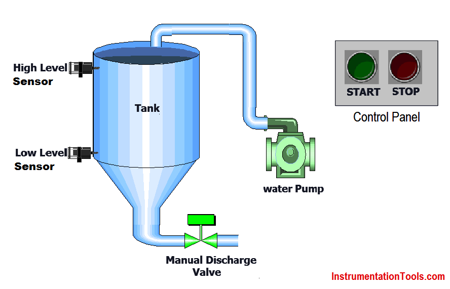
PLC program for Latching and unlatched circuit
Problem Solution

In this example, we consider one storage tank for water and use one water pump for tank filling.

We also use one level sensor for high level and control panel for operator.

Here START PB for enabling the motor so we can feed the water in the tank, for stop motor we use STOP PB.

Level sensor for detection of High level so when tank becomes full, high level sensor will be activated and stops the water pump.

For this sequence we will use SET and RESET instruction for latching and unlatching the water pump.

We can make this circuit by sing relays.

In application there one manual discharge valve only for discharging the tank manual. We will not consider in or logic.

PLC Inputs List

  • START PB : I0.0
  • STOP PB : I0.1
  • HIGH LEVEL SENSOR : I0.2
  • LOW LEVEL SENSOR : I0.3

PLC Outputs List

  • WATER PUMP : I0.0

PLC Ladder diagram for Latching and unlatched circuit

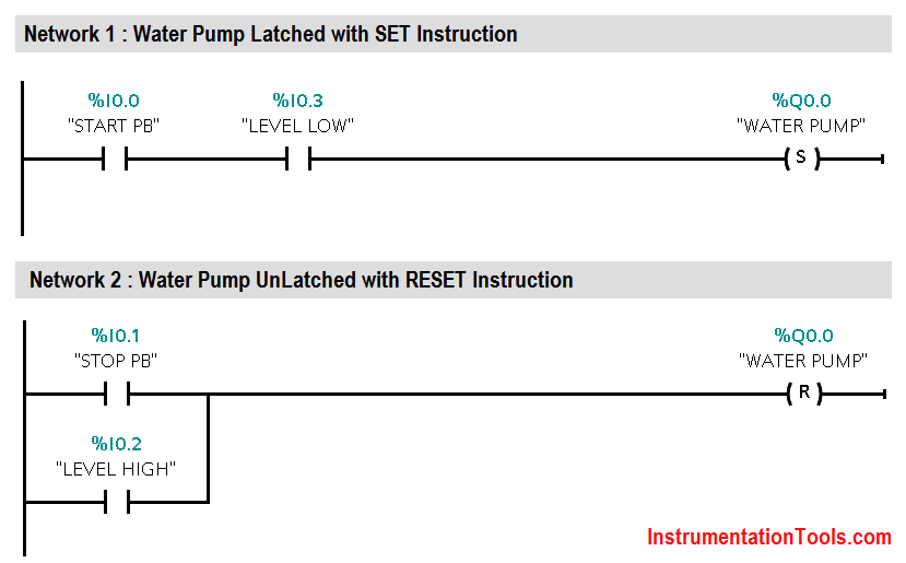
PLC Ladder Logic using SET and RESET Instructions
Program Description

  • For this application we use S7-1200 PLC and TIA portal software for programming. We can make this circuit or logic with relay also.
  • This circuit or logic known as latching and unlatching circuit or logic.
  • We will write logic for water pump in Network 1. Here we use NO contact of START PB (I0.0) for enabling the water pump (Q0.0).
  • By using SET instruction water pump output coil (Q0.0) will be latched.
  • Add NO contact of LEVEL LOW SENSOR (I0.3) in series with the water pump output (Q0.0).
  • Water pump should not start if tank is full. so for safety purpose use one NO contact of LOW LEVEL SENSOR (I0.3) in series after START PB (I0.0) in Network 1.
  • Now HIGH LEVEL SENSOR (I0.2) will be detected after some time of pump running and in this case water pump (Q0.0) should be stopped automatically. For that purpose we need to unlatch the circuit.
  • We will write logic for unlatching circuit in Network 2. In this case,  we take No contact of HIGH LEVEL SENSOR (I0.3) for unlatching the circuit by using RESET instruction.
  • Add one NO contact of STOP PB (I0.1) in parallel connection, so operator can unlatch the circuit by pressing STOP PB (I0.1).
  • Here we latch circuit by SET instruction and unlatch with RESET instruction.

Runtime Test Cases
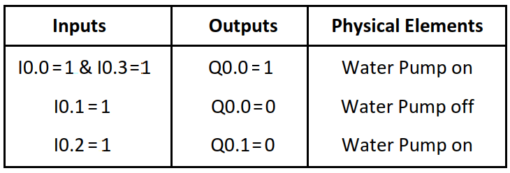
latching and unlatching circuit

Note: The above PLC Logic provided for basic idea about application of PLC Program for Latching and unlatching Circuit. The Logic is limited and not complete application.

Author: Bhavesh

If you liked this article, then please subscribe to our YouTube Channel for PLC and SCADA video tutorials.

You can also follow us on Facebook and Twitter to receive daily updates.

Read Next:

  • PLC Programming Questions & Answers
  • Sequence of Conveyors with Interlock
  • Motor Operation based on Time Cycle
  • PLC Tank Heating Control using Heater
  • Heating and Mixing of Products using PLC
Don't Miss Our Updates
Be the first to get exclusive content straight to your email.
We promise not to spam you. You can unsubscribe at any time.
Invalid email address
You've successfully subscribed !

Continue Reading

Communication between Factory IO and Siemens Tia Portal
Allen Bradley Bitwise Logical Operations
Understanding the Scan Cycle of SIEMENS PLC
Difference Between Industrial Computer (IPC) and Normal Computer (PC)
Free Schneider PLC Training – Automation Course
Heating and Mixing of Products using PLC Example Tutorial
Share This Article
Facebook Whatsapp Whatsapp LinkedIn Copy Link
Share
3 Comments
  • rahim says:
    June 20, 2018 at 4:25 pm

    Thank you .
    These kind of examples help to learn PLC programming .Kindly continue and give harder examples.

    Reply
  • Jairo Francisco Oliveira Paula says:
    August 13, 2019 at 4:01 am

    excelente artigo!

    Reply
  • Aladdin Muaña says:
    April 26, 2021 at 5:12 pm

    Please help me for my activity. Its difficult like me as first timer.
    Here is the problem.

    When you press Push Button (PB1) – X21 the output bulb (YO) will lit… When you release the PB1 the output bulb will off.

    Reply

Leave a Reply Cancel reply

Your email address will not be published. Required fields are marked *

Stay Connected

128.3kFollowersLike
69.1kFollowersFollow
210kSubscribersSubscribe
38kFollowersFollow

Categories

Explore More

PLC Programming Best Practices and Tips
Wet Contacts and Dry Contacts in PLC Systems
Cloud-Based SCADA Projects – Try Free Demo Account
Create a Function (FC) for a Valve Logic in Siemens PLC
Industrial Automation Engineers Interview Questions
What is Marshalling Cabinet?
Learn PLC in Hindi
Sorting & Distribution Line PLC Programming – Advanced Logic

Keep Learning

Cars Garage Counter From the Same Door PLC Logic

Cars Garage Counter From the Same Door PLC Logic

Sharing data between two PLC systems

Distributed IO Sharing Between PLC Systems – Technical Insights

Most Asked Questions on SCADA

Most Asked Questions on SCADA with Answers

Oracle certification program

Oracle Database 12c Administrator Certified Associate Certification

Ladder Logic for Motor Control

PLC Programming for 3 Motors control in Ladder logic

Control of Double-acting Pneumatic Cylinder

Ladder Logic for Control of Double-acting Pneumatic Cylinder

Reading Clock data in PLC

Real-Time Clock in Omron PLC? – CX Programmer

PLC-Complete-Training-Package

Free PLC Training Software Download

Learn More

quadruple block valve

What is Safety Instrumented Functions ?

Hybrid Level Transmitter Principle

Hybrid Level Measurement Principle, Selection, Installation, Limitations and Calibration

Electrical Machines Questions and Answers

Equivalent Circuit of Transformer

Squirrel Cage Induction Motor Synchronous View

Squirrel Cage Induction Motor Animation

Torque Measurement Objective Questions

Torque Measurement Objective Questions

Measurement of Voltage Objective Questions

Measurement of Voltage Objective Questions

Testing and Validation in PLC Development

Testing and Validation in PLC Development

Electrical Machines Questions and Answers

DC Machines Excitation Quiz

Menu

  • About
  • Privacy Policy
  • Copyright

Quick Links

  • Learn PLC
  • Helping Hand
  • Part Time Job

YouTube Subscribe

Follow US
All rights reserved. Reproduction in whole or in part without written permission is prohibited.
Welcome Back!

Sign in to your account

Username or Email Address
Password

Lost your password?