In this article, you will learn the PLC program for Boolean expression and learn the plc automation with basic logic.
Please note: The logic diagram example provided here is designed for educational use for students and engineers to learn PLC fundamentals.
PLC Program
Problem Statement
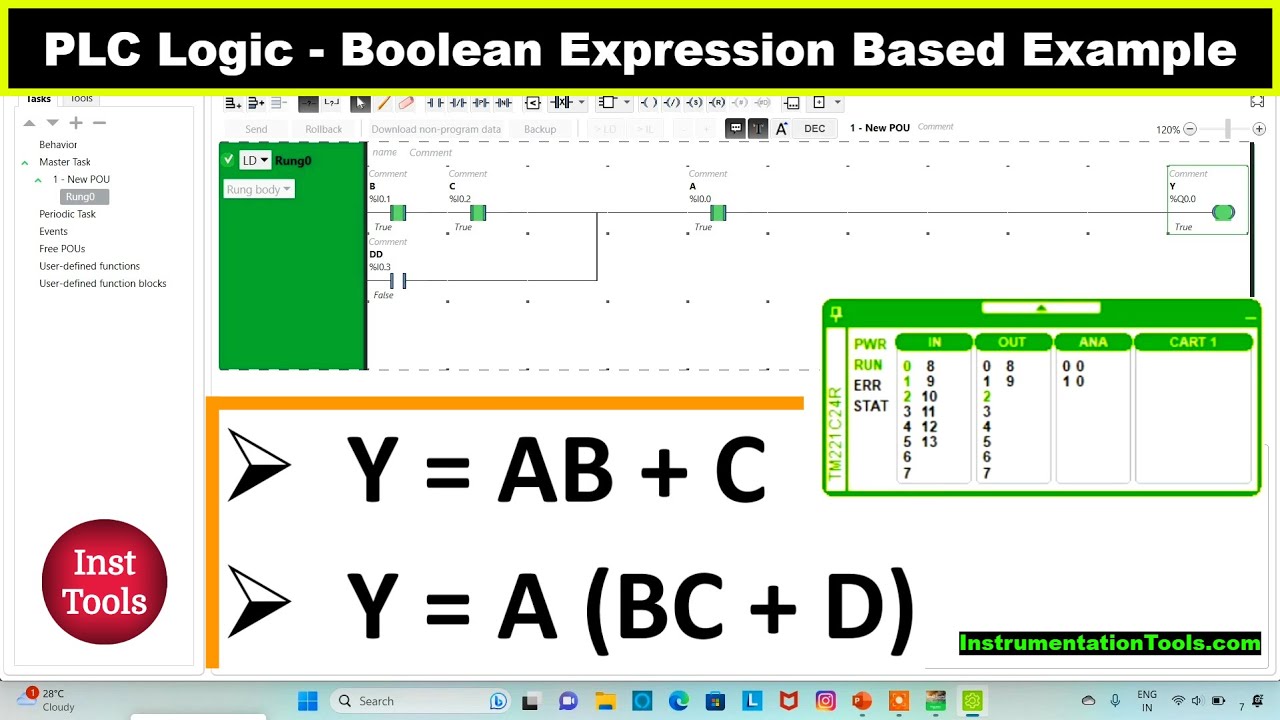
Design a PLC ladder logic for the following Boolean Expression.
We are using toggle Inputs to control the output.
Convert the given boolean logic to PLC ladder logic.
Y = A(BC+D)
Boolean to PLC Conversion
Watch the below PLC tutorial video to learn the basics.
Inputs
Digital Inputs:
The list of inputs are listed.
A: I0.0
B: I0.1
C: I0.2
D: I0.3
Outputs
Digital Outputs:
The list of outputs are listed.
Y: Q0.0
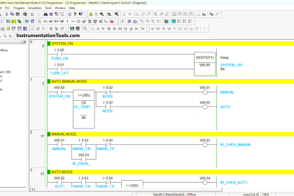
Boolean Expression Ladder Logic
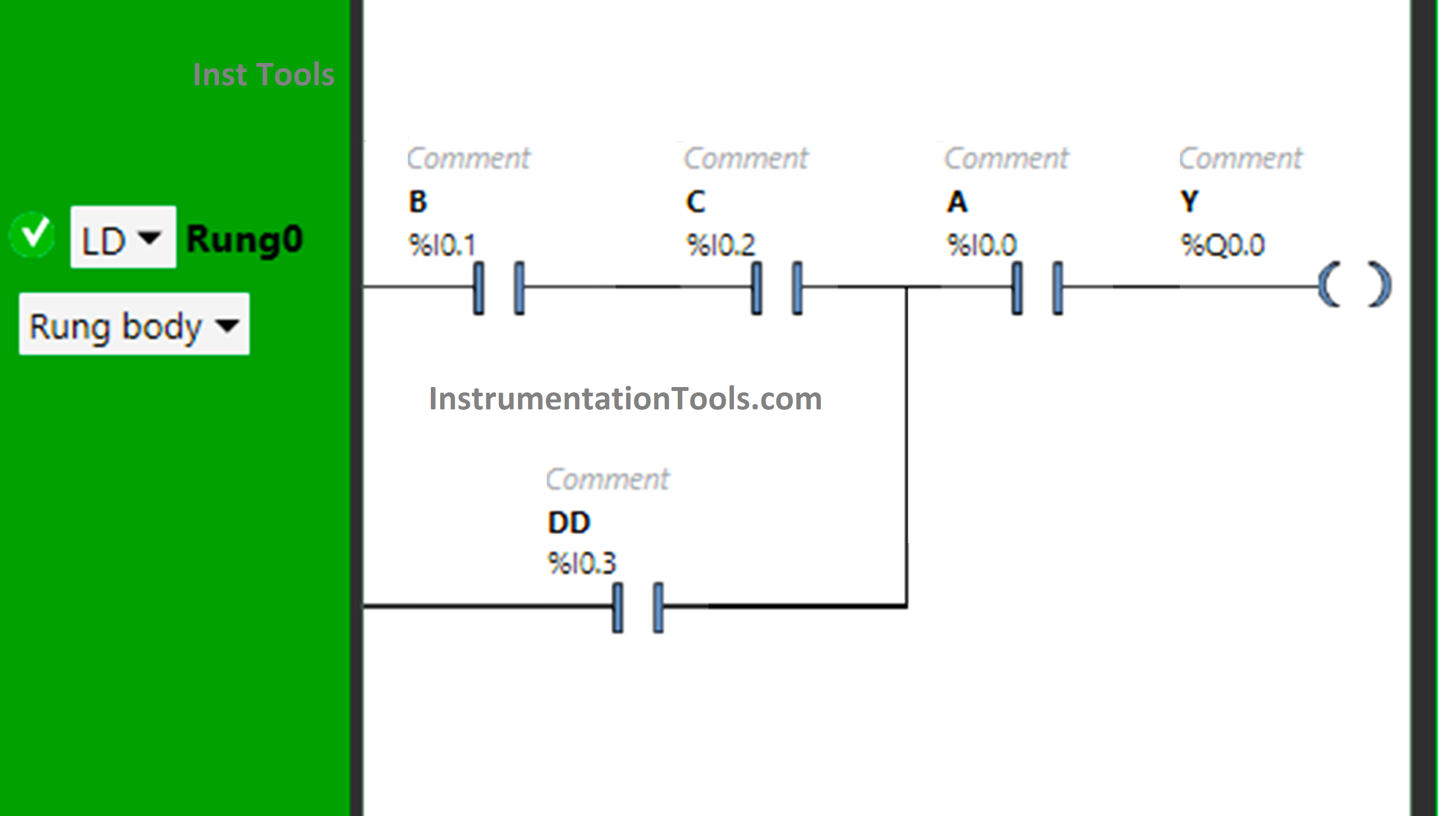
Logic Description
- We used the EcoStruxure Machine Expert Basic software for PLC programming.
- In the above program, Normally Open Contacts are used for inputs A, B, C, and D.
- Input B and Input C are connected in series, thus implementing AND Logic Gate.
- The Input D is connected in parallel with the output of BC, thus implementing OR Logic Gate.
- Then there is again the implementation of AND Logic Gate as the Input A is connected in series with the output of BC+D.
- For output Y (Q0.0) to be ON, either Input B, Input C, and Input A should be ON, or Input D and Input A should be ON.
- Turning OFF Input A will turn OFF Y (Q0.0), even if all remaining Inputs are turned ON.
Test Results
Now we simulate the program with different input statuses.
When Input B, Input C, and Input A are ON
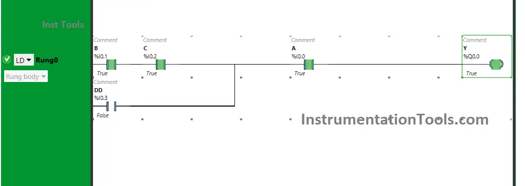
When Input B, Input C and Input A are turned ON, the output Y (Q0.0) will turn ON. If one of these Inputs are turned OFF, Y(Q0.0) is turned OFF. These inputs are used as Normally Open Contacts and are connected in series.
Therefore, all the inputs should be ON so that the output Y (Q0.0) will turn ON. The output Y (Q0.0) will not turn ON, if all the inputs i.e., B, C and D are not turned ON.
When both Input D and Input A are ON
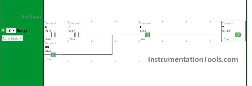
Y (Q0.0) will turn ON When Input D and Input A are turned ON. As the input D is connected in parallel with the output of BC, instead of turning ON the inputs B and C, the input D will also allow the signal to pass when turned ON.
The inputs D and A are connected in series. Therefore, turning ON the inputs D and A will also turn ON the output Y (Q0.0). If only one input is turned ON, the output Y (Q0.0) will not turn ON.
If you liked this article, please subscribe to our YouTube Channel for PLC and SCADA video tutorials.
You can also follow us on Facebook and Twitter to receive daily updates.
Read Next:
- Programmable Logic Controller Test
- Memory Bits and Set Coils in Ladder Logic
- PLC with 2 Toggle Switches and 4 Motors
- PLC based Door Open and Closing System
- DeMorgans Theorems using Ladder Diagram