Create a PLC Program for Automatic Liquid Mixing Application using ladder logic programming. Study about mixing process using a PLC ladder diagram.
Liquid Mixing Application
Problem Description
In many industries, there are lots of mixing system used for solutions mixing. Some plants use complete automation or semi-automation.
In a manual system, there are so many disadvantages such as lack of Accuracy, Time delay problems, loss of liquids, Time consumption, etc.
Here we are discussing the semi-automatic application of a mixing system.
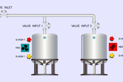
Diagram

Problem Solution
For this example, we use PLC programming and for that we use Siemens S7-1200 PLC.
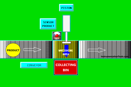
For easy explanation, we can consider simple example of mixing system as shown above.
In this application pure unmixed solution can be prepared by the operator using switches S1 and S2. And mixed solution or material can be prepared by the operator using switch S3.
Operator observes the level of the tank and he can discharge the liquid inside tank by operating valve V5.
Also the agitator motor M will be in running while tank is being filled. We will provide interlock system so operator cannot operate both switches at same time.
V1, V3 and V5 are manual valves which is not connected to the PLC.
V2 and V4 are electronically operated valves which can be controlled by PLC.
List of PLC inputs outputs
Digital Inputs
There are three switches S1, S2 & S3
- S1 : I0.0
- S2 : I0.1
- S3 : I0.3
Digital Outputs
We have two valves V2 & V4. one Agitator Motor M1
- V2 : Q0.0
- V4 : Q0.1
- M1 : Q0.2
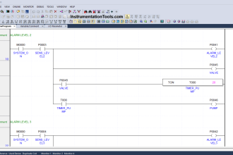
PLC Ladder Diagram for Automatic Liquid Mixing Application

PLC Program Explained
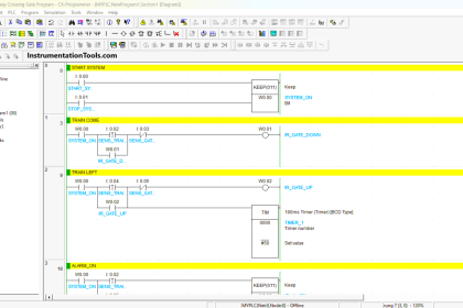
- For this application, we used S7-1200 PLC and TIA portal software for programming.
- In Network 1, we have taken NO contact of S1 (I0.0) and NC contact of S2 (I0.1) and S3 (I0.2) in series. By activating switch S1 operator can START the valve V2 for solution 1 (Liquid 1 ).
- In Network 2, we have taken NO contact of S2 (I0.1) and NC contact of S1 (I0.0) and S3 (I0.2) in series. By activating switch S2 (I0.1) operator can START the valve V4 (Q0.1) for solution 2 (Liquid 2).
- For both Networks 1 & 2, A parallel connection we have taken, NO contact of S3 (I0.2) and in series with NC contact of S1 (I0.0) and S2 (I0.1).
- Because of the above parallel connection, operator can operate both valves by activating switch S3 (I0.2) for mixed solution (Liquid 1 & Liquid 2)
- As per our condition, agitator M1 (Q0.2) should be activated automatically while tank is being filled. So we have taken NO contact of V2 (Q0.1) and in parallel NO contact of V4 (Q0.1) so agitator will be activated automatically by operating any switch.
Runtime Test Cases

Note : The above PLC Logic provided for basic idea about application of PLC in Liquid Mixing Application. The Logic is limited and not complete application.
If you liked this article, then please subscribe to our YouTube Channel for PLC and SCADA video tutorials.
You can also follow us on Facebook and Twitter to receive daily updates.
Read Next:
- Continuous Filling PLC Operation
- Ladder logic program to GE PLC
- PLC Program Backup procedure
- Conveyor Motor PLC Logic
- PLC System Troubleshoot


Tons of teaching information for free,
Thank you so much I am a program Learner.
I have a MicroLogix 1100 processor with basic 10 inputs and 6 outputs. Will add some more IO’s.
Planning to teach electricians and electrical engineers.
Again Thanks
THERE ARE 3 INPUTS 2 OUTPUTS. PLEASE CHECK THE ADDRESS OF COIL Q 0/2 INSTEAD Q 0/3 IN NETWORK #3
I have never seen any diagram. Why
give some information about hmi design