Inst ToolsInst ToolsInst Tools
  • Courses
  • Automation
    • PLC
    • Control System
    • Safety System
    • Communication
    • Fire & Gas System
  • Instrumentation
    • Design
    • Pressure
    • Temperature
    • Flow
    • Level
    • Vibration
    • Analyzer
    • Control Valve
    • Switch
    • Calibration
    • Erection & Commissioning
  • Interview
    • Instrumentation
    • Electrical
    • Electronics
    • Practical
  • Q&A
    • Instrumentation
    • Control System
    • Electrical
    • Electronics
    • Analog Electronics
    • Digital Electronics
    • Power Electronics
    • Microprocessor
  • Request
Search
  • Books
  • Software
  • Projects
  • Process
  • Tools
  • Basics
  • Formula
  • Power Plant
  • Root Cause Analysis
  • Electrical Basics
  • Animation
  • Standards
  • 4-20 mA Course
  • Siemens PLC Course
Reading: PLC Permissive for Motor Control
Share
Font ResizerAa
Inst ToolsInst Tools
Font ResizerAa
  • Courses
  • Design
  • PLC
  • Interview
  • Control System
Search
  • Courses
  • Automation
    • PLC
    • Control System
    • Safety System
    • Communication
    • Fire & Gas System
  • Instrumentation
    • Design
    • Pressure
    • Temperature
    • Flow
    • Level
    • Vibration
    • Analyzer
    • Control Valve
    • Switch
    • Calibration
    • Erection & Commissioning
  • Interview
    • Instrumentation
    • Electrical
    • Electronics
    • Practical
  • Q&A
    • Instrumentation
    • Control System
    • Electrical
    • Electronics
    • Analog Electronics
    • Digital Electronics
    • Power Electronics
    • Microprocessor
  • Request
Follow US
All rights reserved. Reproduction in whole or in part without written permission is prohibited.
Inst Tools > Blog > PLC Tutorials > PLC Permissive for Motor Control

PLC Permissive for Motor Control

Last updated: March 4, 2021 3:51 pm
Editorial Staff
PLC Tutorials Practical Questions
2 Comments
Share
2 Min Read
SHARE

A engineer needs to write a PLC program to control a water pump driven by an electric motor. This water pump will be manually started and stopped by pushbutton switches, and shutdown automatically by any one of several “permissive” switches.

The operating statuses of these switches are listed here:
  • Start pushbutton (normally-open): open when unpressed, closed when pressed
  • Stop pushbutton (normally-open): open when unpressed, closed when pressed
  • Low water level (normally-closed): closed when level is low, open when level is adequate
  • Low oil pressure (normally-open): open when pressure is low, closed when pressure is adequate
  • High vibration (normally-closed): closed when still, open when vibrating
  • Water leak detector (normally-open): open when dry, closed when wet (leak detected)

PLC Permissive Motor Control

The engineer’s first attempt is shown here, but it contains a serious error. Identify and correct this error:
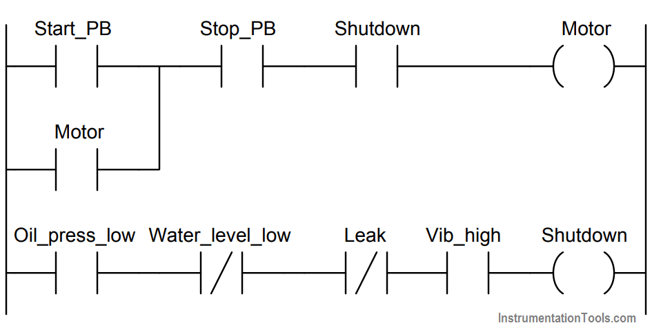
PLC program pushbutton switches

Answer :

The Stop_PB contact instruction should be drawn as normally-closed rather than normally-open as shown in the engineer’s first draft of the PLC program.

The program is designed to shutdown the motor when that pushbutton is pressed (i.e. the Stop_PB contact instruction becomes uncolored (i.e. fails to “conduct” virtual power).

We have been told that the real-world Stop pushbutton switch is NO, which means its contact closes when pressed.

This means pressing the Stop pushbutton causes that bit to be 1, which necessitates an NC contact instruction so that it will un-color under that condition.

If you liked this article, then please subscribe to our YouTube Channel for PLC and SCADA video tutorials.

You can also follow us on Facebook and Twitter to receive daily updates.

Read Next:
PLC Counters Program

Contacts and Coils in PLC

PLC Electric Motor Interlocks

Motor Control Circuit

PLC Pump Permissive

Don't Miss Our Updates
Be the first to get exclusive content straight to your email.
We promise not to spam you. You can unsubscribe at any time.
Invalid email address
You've successfully subscribed !

Continue Reading

Determine the Problems with Level Transmitter and Gauge
Why Use a Current Loop?
Sketch a Ladder Diagram for PLC to Energize the Lamp
Structured Text PLC Example for Motor Interlocking and Control
Loop Check of 4-20mA or HART Transmitters
PLC Compressor Control Ladder Logic
Share This Article
Facebook Whatsapp Whatsapp LinkedIn Copy Link
Share
2 Comments
  • Bruce says:
    April 19, 2018 at 7:09 am

    Why would you show an example of stop being NO and not fail safe. You would never see it wired this way in an individual setting?

    Reply
  • DIMITRIOS ADAMOS says:
    June 21, 2018 at 8:19 pm

    Hi , i believe that there are two ways that you can program a stop button . this is one way that you mention
    and the other way ,you have stop button NC (hardwired) and you program it as NO in the plc ,fail safe .so there is no wrong in this i believe .great work

    Reply

Leave a Reply Cancel reply

Your email address will not be published. Required fields are marked *

Stay Connected

128.3kFollowersLike
69.1kFollowersFollow
210kSubscribersSubscribe
38kFollowersFollow

Categories

Explore More

Types of PLC Memory
Package System Architecture – Control & Instrumentation
Power Supply Sizing for Industrial Automation Systems
#5 PLC Best Practices – Cryptographic and Checksum Integrity Checks
Free SCADA Training Course
Pause the Timer PLC Ladder Logic
CX-Programmer Tutorial: 1 Button To Activate 4 Different Machines
Motor Speed Control using VFD and PLC Programming

Keep Learning

Function Block Programming in Studio 5000

Introduction to Functional Block Diagram in Studio 5000

Calculate Incident Power in Radar Level Measurement

Calculate Incident Power in Radar Level Measurement

Why Are Charcoal and Salt Added to an Earthing Pit

Why Are Charcoal and Salt Added to an Earthing Pit?

Simatic Prosave HMI

How to Backup and Restore from Simatic Prosave HMI?

PLC Load Memory

What is Resources Tab in the Siemens PLC?

Flow Transmitter Readings mismatch with DCS

Flow Transmitter Readings mismatch with DCS

Omron PLC programs

Daily Alarm PLC Program using Real-Time Clock

PC-Based Motion Controller

Various Types of Delta PLC used in Industrial Automation

Learn More

SMART Transmitters Block Diagram

Smart Transmitters LRV & URV

Schematic Diagram

Schematic Diagram

how-to-avoid-bad-grounds

How to Avoid Bad Grounds ?

Gas Detectors Location Installation

Gas Detectors Installation Techniques

RSLogix5000 PLC Program Backup procedure

Simplified Induction Motor - Cross Section

Siemens Standard Drives Application Handbook (PDF)

Types of Flow Meters MCQ - Instrumentation and Control

Types of Flow Meters MCQ – Instrumentation and Control

Radiometric level Principle

Radiometric level measurement Working Principle

Menu

  • About
  • Privacy Policy
  • Copyright

Quick Links

  • Learn PLC
  • Helping Hand
  • Part Time Job

YouTube Subscribe

Follow US
All rights reserved. Reproduction in whole or in part without written permission is prohibited.
Welcome Back!

Sign in to your account

Username or Email Address
Password

Lost your password?