Inst ToolsInst ToolsInst Tools
  • Courses
  • Automation
    • PLC
    • Control System
    • Safety System
    • Communication
    • Fire & Gas System
  • Instrumentation
    • Design
    • Pressure
    • Temperature
    • Flow
    • Level
    • Vibration
    • Analyzer
    • Control Valve
    • Switch
    • Calibration
    • Erection & Commissioning
  • Interview
    • Instrumentation
    • Electrical
    • Electronics
    • Practical
  • Q&A
    • Instrumentation
    • Control System
    • Electrical
    • Electronics
    • Analog Electronics
    • Digital Electronics
    • Power Electronics
    • Microprocessor
  • Request
Search
  • Books
  • Software
  • Projects
  • Process
  • Tools
  • Basics
  • Formula
  • Power Plant
  • Root Cause Analysis
  • Electrical Basics
  • Animation
  • Standards
  • 4-20 mA Course
  • Siemens PLC Course
Reading: PLC Instruction List Example for Level Control of Tank
Share
Notification Show More
Font ResizerAa
Inst ToolsInst Tools
Font ResizerAa
  • Courses
  • Design
  • PLC
  • Interview
  • Control System
Search
  • Courses
  • Automation
    • PLC
    • Control System
    • Safety System
    • Communication
    • Fire & Gas System
  • Instrumentation
    • Design
    • Pressure
    • Temperature
    • Flow
    • Level
    • Vibration
    • Analyzer
    • Control Valve
    • Switch
    • Calibration
    • Erection & Commissioning
  • Interview
    • Instrumentation
    • Electrical
    • Electronics
    • Practical
  • Q&A
    • Instrumentation
    • Control System
    • Electrical
    • Electronics
    • Analog Electronics
    • Digital Electronics
    • Power Electronics
    • Microprocessor
  • Request
Follow US
All rights reserved. Reproduction in whole or in part without written permission is prohibited.
Inst Tools > Blog > PLC Tutorials > PLC Instruction List Example for Level Control of Tank

PLC Instruction List Example for Level Control of Tank

Explore a PLC instruction list example for tank level control and learn the nuances of using instruction list language.

Last updated: March 11, 2025 4:04 pm
Editorial Staff
PLC Tutorials
No Comments
Share
7 Min Read
SHARE

Level control of a tank is the most commonly used system in an automation application. PLC programmers use different types of languages according to their feasibility. One of the languages which is used very less is the instruction list. We can use this language for our purpose here of writing the program for level control. In this post, we will control the level of the tank by using instruction list language and continue from our earlier post where we saw basic instructions like timers and counters written in this language.

Example for Level Control of Tank

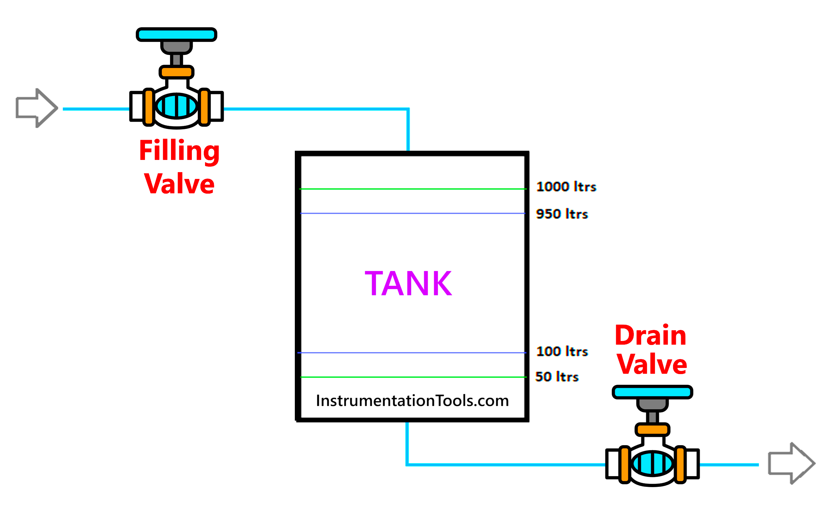
  1. Let us look at the case scenario first. We have a tank which has a level transmitter installed in it, for controlling the valves. There are two valves – one at inlet and one at outlet. The inlet valve is used to fill the tank proportionally, and the outlet valve is used to drain the tank proportionally. Both these proportionate actions take place through the level transmitter. Instead of PID, we will use some simple mathematical formulae for controlling the valves.
  2. For this application, we will use Machine Expert Basic software and write the coding in instruction list language. Following are the PLC inputs – level transmitter. Following are the PLC outputs – filling valve and draining valve.
  3. Refer to the below image. The green lines inside the tank are used for control of the filling valve and the blue lines inside the tank are used for control of the drain valve. When the water is below the green line in the bottom of the tank, the filling valve opens at it’s maximum position. When the water is above the green line in the top of the tank, the filling valve opens at it’s minimum position. When the water is below the blue line in the bottom of the tank, the drain valve opens at it’s minimum position. When the water is above the blue line in the top of the tank, the drain valve opens at it’s maximum position. So, as the water level increases, the drain valve will open and vice-versa for inverse action. When the water level decreases, the filling valve will open and vice-versa for inverse action. In between the lines, three internals level setpoints will be present in the PLC program. When any interval is crossed for the particular valve, that valve will open or close by 20%.
PLC Instruction List Example for Level Control of Tank
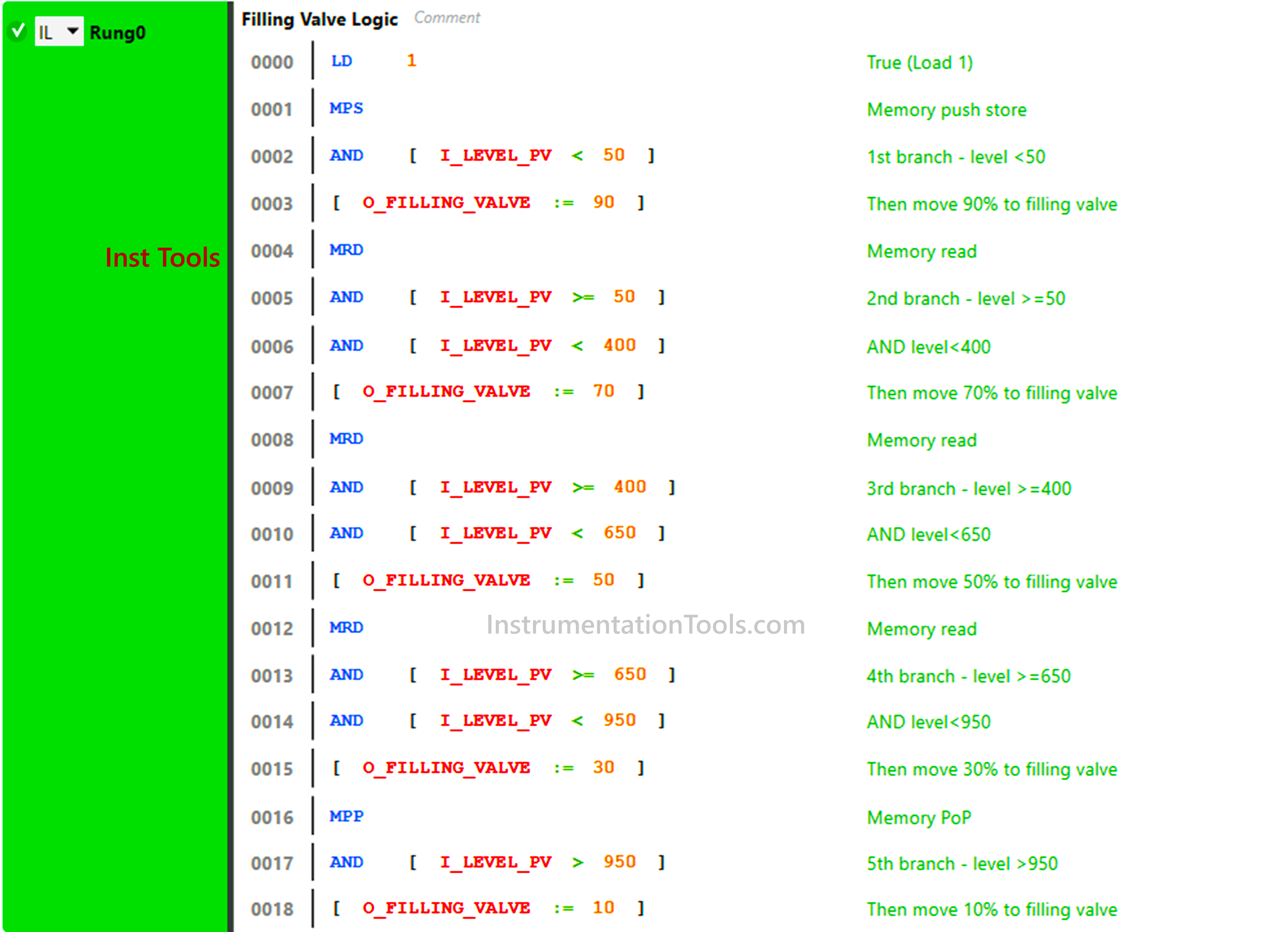
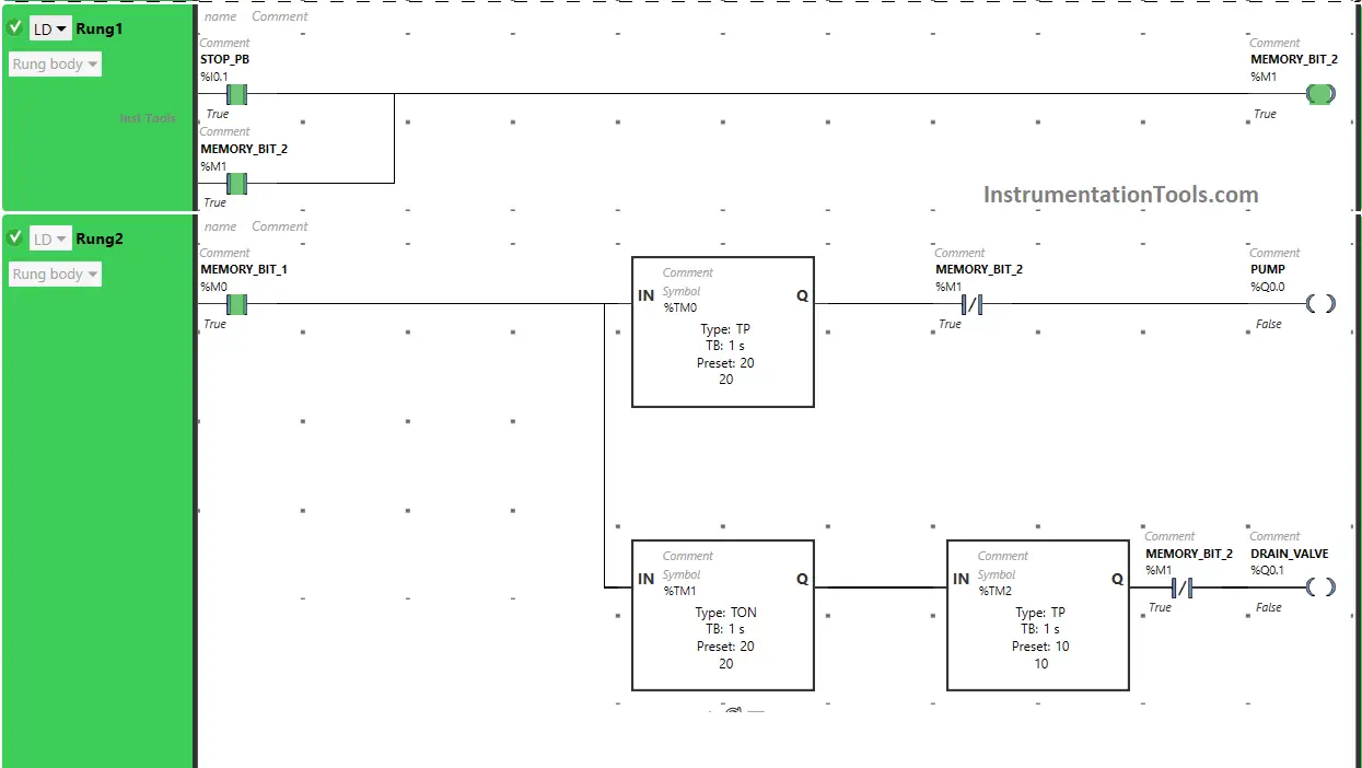
  1. See the first rung below. We will control the filling valve first. We created five cases for this valve. Here, the case refers to the level of the tank. In all the five cases, five different values are moved to the valve. For the five cases, we will create parallel branches to operate the valve. For branches, MPS denotes start of the branch, MRD denotes branch extension and MPP denotes end of the branch. As a branch is created, we use a true variable which continuously supplies power to the rung. In the first branch, if the level is less than 50, then a value of 90 is moved to the valve.  In the second branch, if the level is more than equal to 50 and less than 400, then a value of 70 is moved to the valve. In the third branch, if the level is more than equal to 400 and less than 650, then a value of 50 is moved to the valve. In the fourth branch, if the level is more than equal to 650 and less than 950, then a value of 30 is moved to the valve. In the fifth branch, if the level is more than 950, then a value of 10 is moved to the valve. So, as branches work in OR condition, if any of the branch conditions is true, then the operation will take place.
how to control the level of a tank using instruction list language
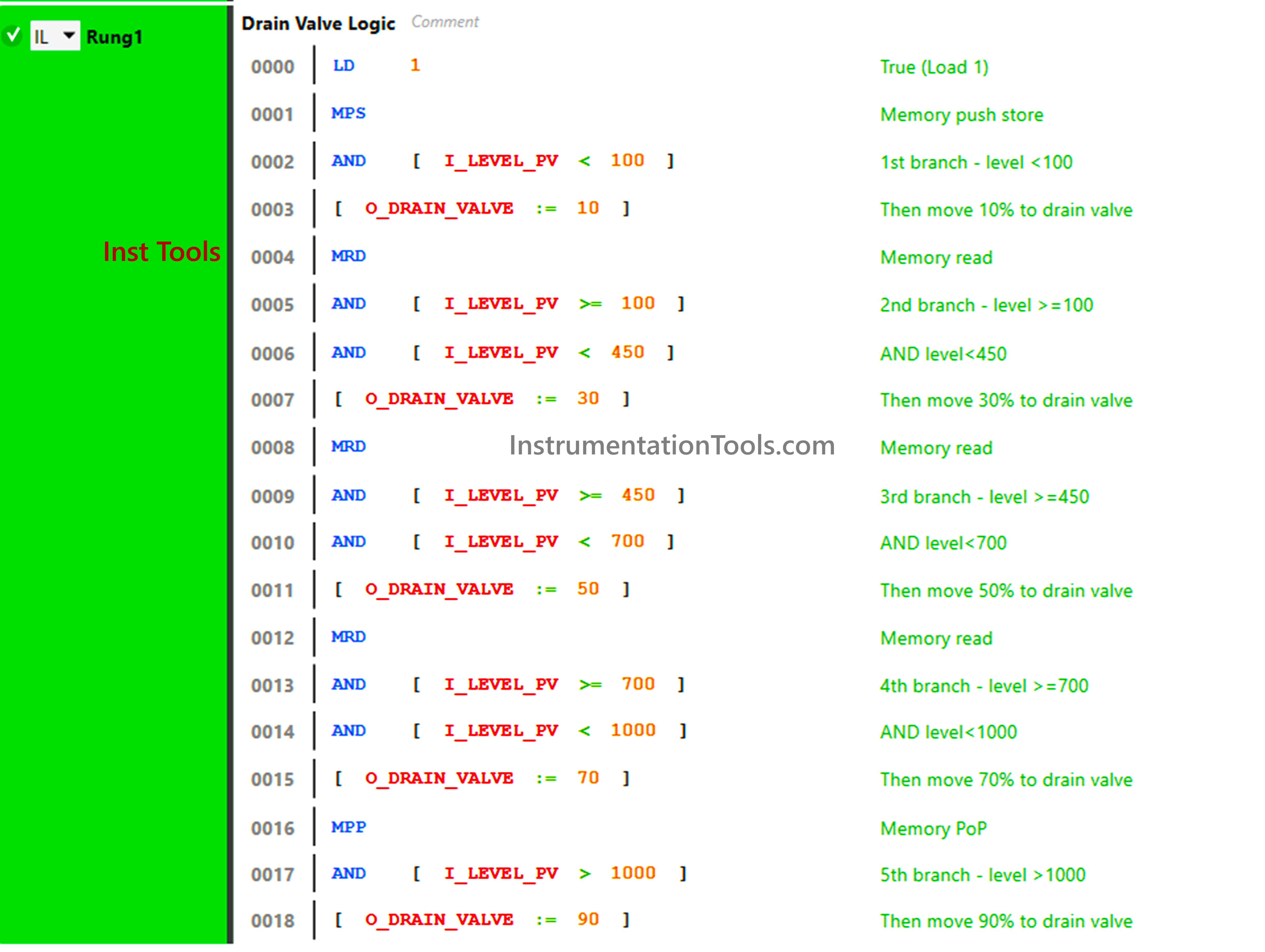
  1. See the second rung below. We will control the drain valve here. We created five cases for this valve. Here, the case refers to the level of the tank. In all the five cases, five different values are moved to the valve. For the five cases, we will create parallel branches to operate the valve. As a branch is created, we use a true variable which continuously supplies power to the rung. In the first branch, if the level is less than 100, then a value of 10 is moved to the valve.  In the second branch, if the level is more than equal to 100 and less than 450, then a value of 30 is moved to the valve. In the third branch, if the level is more than equal to 450 and less than 700, then a value of 50 is moved to the valve. In the fourth branch, if the level is more than equal to 700 and less than 1000, then a value of 70 is moved to the valve. In the fifth branch, if the level is more than 1000, then a value of 90 is moved to the valve. So, as branches work in OR condition, if any of the branch conditions are true, then the operation will take place.
PLC Instruction List Example

In this way, we saw how to control the level of a tank using instruction list language.

Read Next:

  • Light Sequences Structured Text PLC Program
  • Motor Direction Control using Limit Switches
  • Star Delta Starter using Functional Block Diagram
  • While Do Statement in Structured Text PLC Program
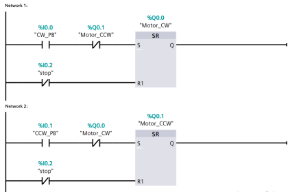
  • PLC Instruction List for Motor Reverse and Forward
Don't Miss Our Updates
Be the first to get exclusive content straight to your email.
We promise not to spam you. You can unsubscribe at any time.
Invalid email address
You've successfully subscribed !

Continue Reading

Set the S5 Timer Value by a Memory Word
Omron PLC Online Training Course
Step-by-Step Guide to Choose Right Fuse for a Panel
ESG in Industrial PLC Automation Systems
PLC Tag Naming Conventions
Difference Between Industrial Computer (IPC) and Normal Computer (PC)
Share This Article
Facebook Whatsapp Whatsapp LinkedIn Copy Link
Share
Leave a Comment

Leave a Reply Cancel reply

Your email address will not be published. Required fields are marked *

Stay Connected

128.3kFollowersLike
69.1kFollowersFollow
210kSubscribersSubscribe
38kFollowersFollow

Categories

Explore More

SCADA Communication and Protocols
HMI Handbook
What are Analog Inputs? – Analog Signals Processing in PLC
Introduction to PLC – Advantages of PLC
Standard Colors in PLC Automation Systems
Siemens S7 300 and STEP 7 PLC program using SIMATIC Software
Making Multi Way Switches using PLC
Problem on PLC, HMI, VFD, and Motor Circuit

Keep Learning

Electrical Drives Animation

Electrical Drives – Modes, Types, Speed Control Applications

Best Practices of PLC Wiring

Best Practices of PLC Wiring – Programmable Logic Controller

Free Download PLC Book

#10 PLC Best Practices – Assign Register Blocks by Function

What is an instruction list language?

Structured Text vs. Instruction List for PLC Programming

PLC Structured Text Program for Output Generation via Equations

PLC Structured Text Program for Output Generation via Equations

PLC Program

Example PLC Program

Simatic Prosave HMI

How to Backup and Restore from Simatic Prosave HMI?

Studio 5000 Logix Emulate Controller

How to Create New Project in Studio 5000?

Learn More

Omron PLC programs

Daily Alarm PLC Program using Real-Time Clock

Key Facts About RS485 Industrial Network

Key Facts About RS485 Industrial Network

PLC Program for Stage Control Curtains and Stage Elevation

PLC Program for Stage Control: Curtains and Stage Elevation

Resistor Y and Delta Network Calculation

Y and Delta Resistor Network Calculations

Conductivity Analyzer Principle

Conductivity Analyzers Interview Questions & Answers

Scaling in PLC

PLC Ladder Logic for Sensor Scaling with Offset

Bagging Machine Controller

Bagging Machine Controller – Principle, Operation Sequence

level gauge

Basics of Sight Glass Level Gauge

Menu

  • About
  • Privacy Policy
  • Copyright

Quick Links

  • Learn PLC
  • Helping Hand
  • Part Time Job

YouTube Subscribe

Follow US
All rights reserved. Reproduction in whole or in part without written permission is prohibited.
Welcome Back!

Sign in to your account

Username or Email Address
Password

Lost your password?