The PLC example on switch program to control the output 1 and output 2 status based on the timers value.
Note: These PLC programs are designed for engineering students and beginners to understand the basics.
PLC Example on Switch Program
Problem Statement:
Design a PLC ladder logic for the following application.
We are using one switch to control 2 outputs.
When the Switch is turned ON, Output 1 and Output 2 will be ON.
When the Switch is turned OFF, Output 1 will be OFF after 10 seconds and Output 2 will be OFF after 15 seconds.
Best Industrial Automation Videos
Instrumentation Tools provides you the best industrial automation videos for training the students all-over the world.
Inputs & Outputs
Digital Inputs:
Switch: I0.0
Digital Outputs:
Output 1: Q0.0
Output 2: Q0.1
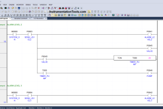
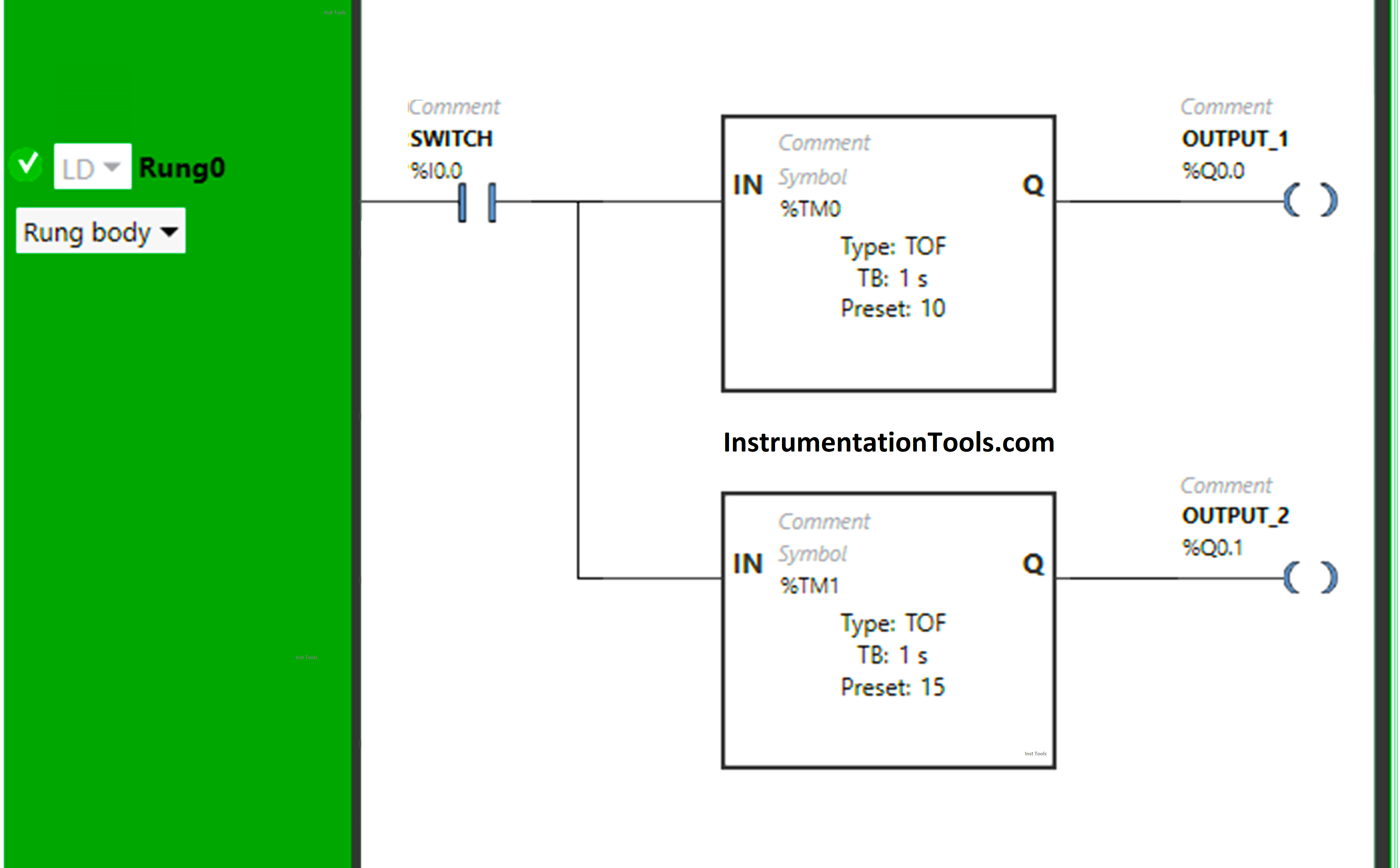
Ladder Logic
Program Description
We have used Normally Open Contact for Switch (I0.0).
In Rung 0:
- Normally Open Contact is used for Switch (I0.0) to Turn ON Output 1 (Q0.0) and Output 2 (Q0.1).
- Timer-type TOF is used to delay the turning OFF time of the Output 1 (Q0.0) for some time.
- Another Timer-type TOF is used to delay the turning OFF time of the Output 2 (Q0.0) for some time.
Simulation Result
Now we simulate the PLC program and check the results.
When Switch (I0.0) is turned ON
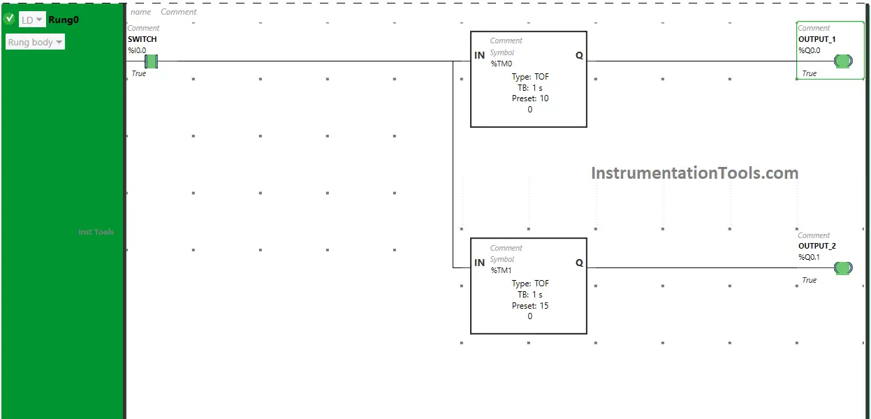
When Switch (I0.0) is turned ON, the signal will flow through Switch (I0.0) as Normally Open Contact used for Switch (I0.0) will be in True State and Output 1 (Q0.0) & Output 2 (Q0.1) will turn ON.
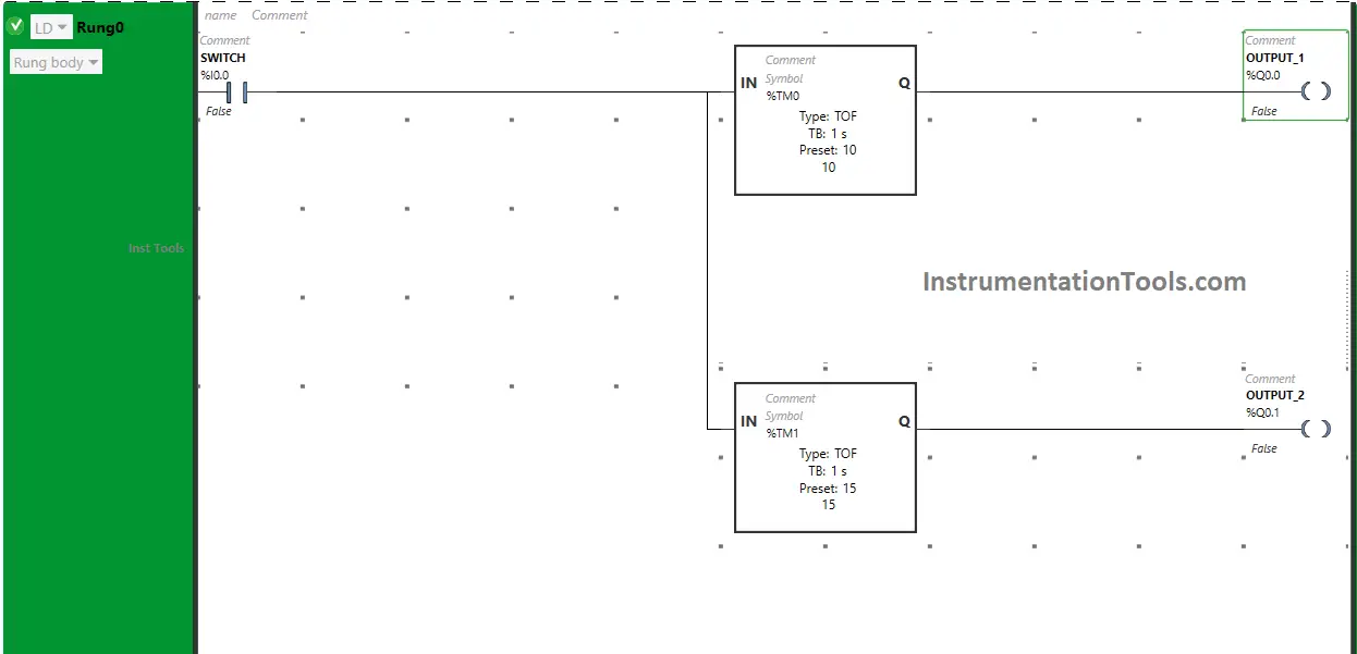
When Switch (I0.0) is turned OFF
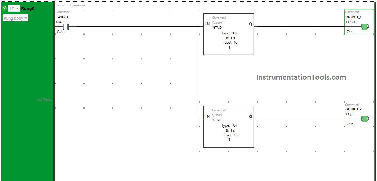
When Switch (I0.0) is turned OFF, the output 1 (Q0.0) remains ON but for a limited time because Timer Function Block type TOF is used to delay the turning OFF time of the output 1 (Q0.0) and time is set to 10 seconds.
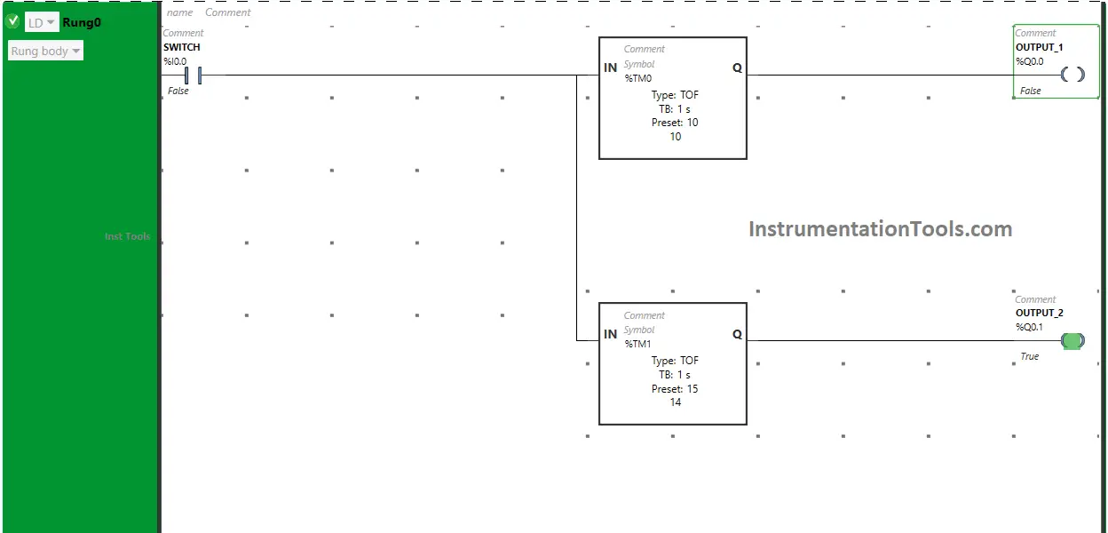
After 10 seconds, the output 1 (Q0.0) will turn OFF.
Also, When Switch (I0.0) is turned OFF, the output 2 (Q0.0) remains ON but for limited time because another Timer Function Block type TOF is used to delay the turning OFF time of the output 2 (Q0.0) and time is set to 15 seconds.
After 15 seconds, the output 2 (Q0.0) will turn OFF.
If you liked this article, please subscribe to our YouTube Channel for PLC and SCADA video tutorials.
You can also follow us on Facebook and Twitter to receive daily updates.
Read Next:
- PLC Program for Two-Way Switch Logic
- PLC Scaling Program for Control Valve
- PLC Automatic Pedal Switch Program
- PLC Programming using Limit Switch
- Making Multi-Way Switches using PLC