This is a PLC Program to start a Belt Conveyor and also make it selectable from where you want to start a conveyor from Local or Remote. Design SCADA graphics also.
By using PLC and SCADA, prepare a PLC program to start a belt conveyor. Also make it selectable from where you want to start Local or Remote. All the interlocks must be included in the program and also design a SCADA graphics.
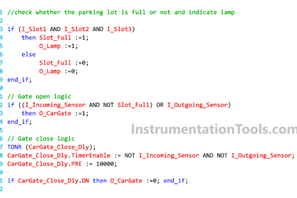
Conveyor Ladder Logic

Problem Solution:
- To make a complete logic first, we have prepared a control as well as power diagram of the starter.
- Then we define the inputs and outputs.
- We have done the wiring from PLC to Starter and Feedback from Field to PLC.
- For the Program, first check all signals from the fields are healthy.
- Then we have prepared a local start/stop logic.
- For healthy running, check all the interlocks from the fields are ok.
- If there will be any fault, then we have activated Error signal.
- After preparing a PLC program we heave design a SCADA in which all the signals are clearly indicated.
Control & Power Diagram:

PLC Inputs and Outputs

PLC Program:
Here is the PLC program to start the belt conveyor with interlocks.
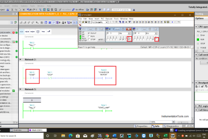
OB1:

Network 1 :

In this Network 1, we are checking whether the belt is ready to start.
This signal will come when all the conditions are healthy as well as safety and power feedback’s are active.
Network 2 :

In the Network 2, When selection of start command is in LOCAL mode then this logic will work.
When start button is pressed from the local operating box Belt_DO bit will be set if Ready_to_Start and No Error will be there.
Network 3 :

This is the local stop logic, this will only work when the selection command is in LOCAL mode.
When stop button is pressed from the local operating box it will reset the Belt_DO bit.
Network 4 :

In this Network 4, this logic is required for safety as soon as Belt_DO bit will set and if any case contactor will not operate due to any fault or Zero speed sensor does not detect pulse then after predefined wait time, here we considered it as Run_FB_Time, it will reset the Belt_DO bit and generate Error.
This Error you can acknowledge from the SCADA after resolving the error from the field side.
Network 5 :

In this Network 5, All the interlocks are taken in line. If any one of this interlock will become active, then it will reset Belt_DO bit and generate Error.
This Error you can acknowledge from the SCADA after resolving the error from the field side.
SCADA Design :

This is a SCADA screen where operator can operate and visually inspect all the parameter of the conveyor belt.
All the indications are marked just for detailing purpose here.
- Operator can change the REMOTE/LOCAL mode by just clicking on the LOCAL or REMOTE text.
- Operator can see the status of READY, ERROR, BSS (Belt Sway Switch), PCS (Pull Chord Switch), ZSS (Zero Speed Switch) as well as LOCAL START and LOCAL STOP button on the operating box.
- Operator can acknowledge ERROR by just clicking ACK button, just after clearing the error from the field side.
- Operator can START/STOP the belt conveyor from the ON and OFF button while the selection in REMOTE mode.
Take a look at some screenshots
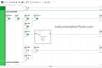
SCADA Ready

This screenshot (above) shows a online monitor of PLC Program as well as SCADA run time screen. There are a healthy signal from Safety button and Power MCCB, so the conveyor belt are showing healthy ready to start indication.
SCADA Run

Here we have already given START command from local operating box (as shown in above picture), the belt is showing RUNNING (Green Color in Belt Symbol means it is running smoothly).
There is a healthy ZSS (Zero Speed Switch) signal from the field and there is no ERROR.
SCADA Error

There is an ERROR bit activated here due to someone is operated PCS (Pull Chord Switch) in the field. So, both ERROR and PCS indication are healthy in SCADA screen as well as we can check in online PLC program as well.
If you liked this article, then please subscribe to our YouTube Channel for PLC and SCADA video tutorials.
You can also follow us on Facebook and Twitter to receive daily updates.
Read Next:
Traffic Light Control using PLC
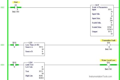
How PLC Reads from Transmitter
PLC Control of 2 Outputs with 1 Input
Contacts and Coils in Ladder Logic


In the power diagram called “belt conveyor drawing,” why is the MCCB numbered as 120 and 130 for its normally open contacts, and not 128 and 129 as it is on the power diagram? Many thanks.