Inst ToolsInst ToolsInst Tools
  • Courses
  • Automation
    • PLC
    • Control System
    • Safety System
    • Communication
    • Fire & Gas System
  • Instrumentation
    • Design
    • Pressure
    • Temperature
    • Flow
    • Level
    • Vibration
    • Analyzer
    • Control Valve
    • Switch
    • Calibration
    • Erection & Commissioning
  • Interview
    • Instrumentation
    • Electrical
    • Electronics
    • Practical
  • Q&A
    • Instrumentation
    • Control System
    • Electrical
    • Electronics
    • Analog Electronics
    • Digital Electronics
    • Power Electronics
    • Microprocessor
  • Request
Search
  • Books
  • Software
  • Projects
  • Process
  • Tools
  • Basics
  • Formula
  • Power Plant
  • Root Cause Analysis
  • Electrical Basics
  • Animation
  • Standards
  • 4-20 mA Course
  • Siemens PLC Course
Reading: P&ID Guidelines for Pumps
Share
Font ResizerAa
Inst ToolsInst Tools
Font ResizerAa
  • Courses
  • Design
  • PLC
  • Interview
  • Control System
Search
  • Courses
  • Automation
    • PLC
    • Control System
    • Safety System
    • Communication
    • Fire & Gas System
  • Instrumentation
    • Design
    • Pressure
    • Temperature
    • Flow
    • Level
    • Vibration
    • Analyzer
    • Control Valve
    • Switch
    • Calibration
    • Erection & Commissioning
  • Interview
    • Instrumentation
    • Electrical
    • Electronics
    • Practical
  • Q&A
    • Instrumentation
    • Control System
    • Electrical
    • Electronics
    • Analog Electronics
    • Digital Electronics
    • Power Electronics
    • Microprocessor
  • Request
Follow US
All rights reserved. Reproduction in whole or in part without written permission is prohibited.
Inst Tools > Blog > Erection & Commissioning > P&ID Guidelines for Pumps

P&ID Guidelines for Pumps

Last updated: September 29, 2016 3:06 pm
Editorial Staff
Erection & Commissioning
1 Comment
Share
3 Min Read
SHARE

P&ID Guidelines for Pumps

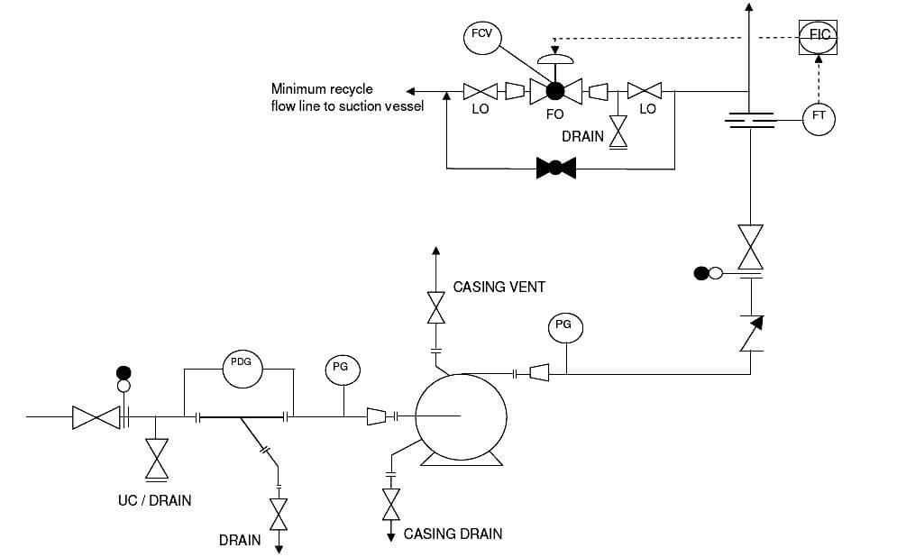
  1. Proper pump symbol should be selected first of all, as shown in the presented drawing. This should be selected from the list of equipment symbols on the legend sheets of a particular project.
  2. All the nozzles on the pump should then be correctly represented with size and flanges. This includes inlet and outlet nozzles and casing drains and vents as shown in the sample drawing presented here. Generally, the suction and discharge nozzles on the pump are smaller than suction and discharge line sizes. Appropriate reducer / expander to be clearly indicated in such cases.
  3. Inlet and outlet lines are the next to be drawn up. Line number, material class, size etc. is to be correctly assigned to each of the lines.
  4. Isolation valves, spectacle blinds, spacers etc. to be used for maintenance should be drawn up next on the inlet / outlet lines. The isolation valves on suction and discharge lines should be ‘Locked Open’ in case of automatic pump start-up.
  5. Inlet line to the pump is to be fitted with a strainer for pump protection. This strainer can be equipped with a pressure differential gauge to monitor blockage in the strainer.
  6. Pressure gauges are normally to be provided on suction and discharge of the pump. In addition, pressure transmitters connected to Emergency Shutdown (ESD) system can also be provided as per requirements.
  7. A check valve should be normally provided on the pump discharge to avoid reverse flow when the pump is not in operation.
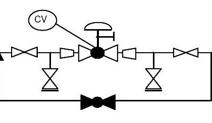
  8. Downstream to the check valve on the pump discharge, minimum flow recirculation line for the pump needs to be provided. A flowmeter should be provided before the minimum flow line, as shown on the presented sample drawing.
  9. A flow control valve with or without bypass is then to be provided on the minimum flow recirculation line. The isolation valves for this control valve need to be locked open or sealed open and the FCV should be of ‘Fail Open’ type. The minimum recirculation line is normally routed back to the suction vessel of the pump.
  10. Drains and vents to be provided on the suction / discharge lines, minimum flow line and on pump casing, so that the pump and associated piping can be completely drained for maintenance.
  11. For purging the pump with nitrogen, a connection should be provided right after isolation valve on the suction line. This connection can also be used as a drain.
  12. Temperature gauges and transmitters to be provided as per requirements for operating and controlling the equipment.
  13. All the guidelines given here are very general and may be modified as per specific requirements of any particular project.
Don't Miss Our Updates
Be the first to get exclusive content straight to your email.
We promise not to spam you. You can unsubscribe at any time.
Invalid email address
You've successfully subscribed !

Continue Reading

DP Level Measurement Problems
What is Piping and Instrumentation Diagram (P&ID) ?
How to Install a Rotameter
Control Valves Pre-Commissioning Checklist
What is Instrument Hook Up Diagram ?
What is Process Flow Diagram (PFD) ?
Share This Article
Facebook Whatsapp Whatsapp LinkedIn Copy Link
Share
1 Comment
  • Kasonde Nsofwa says:
    November 30, 2019 at 2:16 pm

    Why don’t you offer cheaper online programs Instrumentation? Or even scholarship’s to us who would want to upgrade?

    Reply

Leave a Reply Cancel reply

Your email address will not be published. Required fields are marked *

Stay Connected

128.3kFollowersLike
69.1kFollowersFollow
210kSubscribersSubscribe
38kFollowersFollow

Categories

Explore More

Flow Meter Installation Guidelines
What is FAT and SAT? Difference between them
Wrong Installation of Horn Type Radar Level Transmitter on Sloping Tank
Thermocouple Temperature Measurement Errors
Instrumentation Cables Questions & Answers
P&ID Guidelines for Centrifugal Compressor Systems
P&ID Guidelines for Pressure Safety Valves
Impulse Tubing Leak Test Checks

Keep Learning

Basics of Ground Loops

Basics of Ground Loops

Wrong Orifice Installation

How Not to Install an Instrument and Wrong Practices

Common Causes of Imperfect Bends

Instrument Tube Fitting Installation – Part 3

Installation and Calibration of Pressure Transmitter

Installation and Calibration of Pressure Transmitter

Good and Bad Wiring Practices

How to Install Ultrasonic Level Transmitters 5

How to Install Ultrasonic Level Transmitters

How to Solve Cable Tray Sagging

How to Solve Cable Tray Sagging ?

Important Factors Consider during Piping Design

Important Factors Consider during Piping Design

Learn More

4-20ma-formulas-and-examples

4-20mA Formulas and Examples

Digital Electronics Multiple Choice Questions

Memory Devices Objective Questions – Part 4

OMRON PLC program for waste-burning automation

Waste-Burning System OMRON PLC Program Example

PLC Water Project

Smart Spray System using Wecon PLC

Electric Circuits Objective Questions

Electric Circuits Objective Questions – Set 2

The Importance of Supply Chain Collaboration

The Importance of Supply Chain Collaboration

Power Electronics Objective Questions

Voltage Control in Inverters Objective Questions

Instrumentation Loop Diagram

Loop diagram and System Inspection Lab Exercise

Menu

  • About
  • Privacy Policy
  • Copyright

Quick Links

  • Learn PLC
  • Helping Hand
  • Part Time Job

YouTube Subscribe

Follow US
All rights reserved. Reproduction in whole or in part without written permission is prohibited.
Welcome Back!

Sign in to your account

Username or Email Address
Password

Lost your password?