Inst ToolsInst ToolsInst Tools
  • Courses
  • Automation
    • PLC
    • Control System
    • Safety System
    • Communication
    • Fire & Gas System
  • Instrumentation
    • Design
    • Pressure
    • Temperature
    • Flow
    • Level
    • Vibration
    • Analyzer
    • Control Valve
    • Switch
    • Calibration
    • Erection & Commissioning
  • Interview
    • Instrumentation
    • Electrical
    • Electronics
    • Practical
  • Q&A
    • Instrumentation
    • Control System
    • Electrical
    • Electronics
    • Analog Electronics
    • Digital Electronics
    • Power Electronics
    • Microprocessor
  • Request
Search
  • Books
  • Software
  • Projects
  • Process
  • Tools
  • Basics
  • Formula
  • Power Plant
  • Root Cause Analysis
  • Electrical Basics
  • Animation
  • Standards
  • 4-20 mA Course
  • Siemens PLC Course
Reading: P&ID Guidelines for Pig Receivers
Share
Font ResizerAa
Inst ToolsInst Tools
Font ResizerAa
  • Courses
  • Design
  • PLC
  • Interview
  • Control System
Search
  • Courses
  • Automation
    • PLC
    • Control System
    • Safety System
    • Communication
    • Fire & Gas System
  • Instrumentation
    • Design
    • Pressure
    • Temperature
    • Flow
    • Level
    • Vibration
    • Analyzer
    • Control Valve
    • Switch
    • Calibration
    • Erection & Commissioning
  • Interview
    • Instrumentation
    • Electrical
    • Electronics
    • Practical
  • Q&A
    • Instrumentation
    • Control System
    • Electrical
    • Electronics
    • Analog Electronics
    • Digital Electronics
    • Power Electronics
    • Microprocessor
  • Request
Follow US
All rights reserved. Reproduction in whole or in part without written permission is prohibited.
Inst Tools > Blog > Erection & Commissioning > P&ID Guidelines for Pig Receivers

P&ID Guidelines for Pig Receivers

Last updated: September 29, 2016 2:58 pm
Editorial Staff
Erection & Commissioning
No Comments
Share
5 Min Read
SHARE
Typical P&ID arrangement for Pig Receivers
 
pid-guidelines-for-pig-receivers

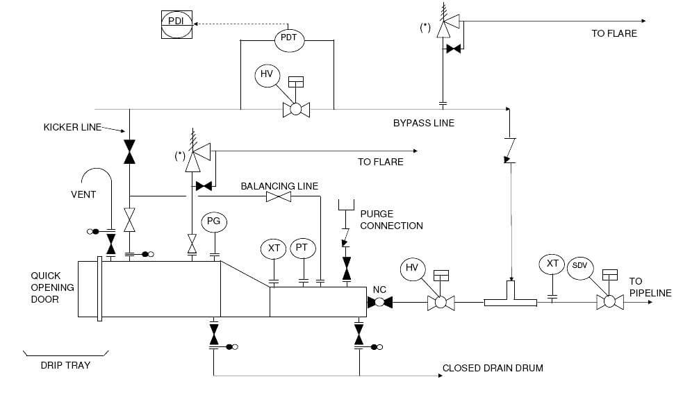
Pig launchers and receivers are commonly used in upstream oil and gas industry for periodic cleaning of pipelines carrying crude oil, natural gas and water from oil wells. A pig is a bullet shaped object which fits the pipeline from inside. The pig launcher launches the pig into pipeline and the upstream pressure pushes the pig to other end of the pipeline where it is received by the pig launcher. Hence generally arrangement for pig launchers and receivers are essentially the same, except for the difference between ‘Kicker line’ position for launchers and receivers. The sample drawing presents this general arrangement common to pig launchers and receivers.

  1. Proper equipment symbol for pig launcher (vertical or horizontal) should be selected first of all, as shown in the presented drawing. This should be selected from the list of equipment symbols on the legend sheets of a particular project.
  2. The major and minor barrels of the pig trap should be indicated as shown in the sample drawing. Minor barrel size is equal to pipeline size and the major barrel size is slightly larger.
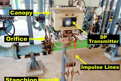
  3. All the nozzles on the pig launcher should then be correctly represented with size and flanges. This includes door on the launcher, pig outlet to pipeline, kicker line, balancing line, PSV connection, purge, vent, drain and instrument nozzles, as shown in the sample drawing presented here. Typicalinstrumentation on the pig launcher would be pressure gauges and transmitters and pig indicators to know if the pig has been launched (or arrived in the case of pig receivers).
  4. Different lines connected to the pig launcher are the next to be drawn up. Line number, material class, size etc. is to be correctly assigned to each of the lines.
  5. Kicker line is used to pressurize the upstream side of pig so it can be launched. In case of receiver, kicker line provides an outlet for fluids arriving in the pig trap. Normally when pigging is not being performed, kicker line is closed using normally closed valve.
  6. Balancing line connecting the kicker line to minor barrel of the pig launcher, helps lower the pressure differential so that sudden shooting of the pig will not damage downstream automatic valves.
  7. A bypass line of the pig launcher is the normal route for the fluids when pigging is not taking place. This section upstream to the shutdown valve at beginning of pipeline can be protected against overpressure as indicated in the sample drawing.
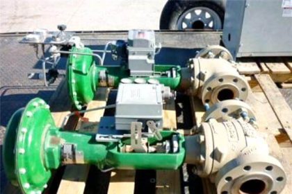
  8. The hand operated valve (HV) on the bypass line is used to create a pressure differential for launching the pig (also for receiving the pig). A pressure differential indicator (PDI) has to be available to the HV operator to monitor the pressure differential.
  9. On the outlet of the pig launcher, another hand operated automatic valve is provided to open up the launcher upon pressurization.
  10. The pig launcher (and receiver) are also protected against overpressure with a PSV which discharges to flare. Typical representation of PSVs can be referred to in another article.
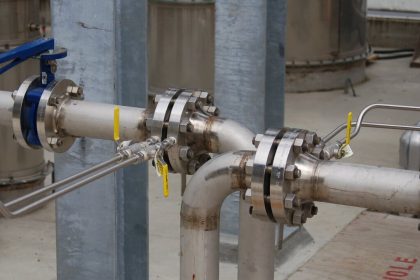
  11. Isolation valves, spectacle blinds, spacers etc. to be used for maintenance should be drawn up next, on various lines to and from the pig trap. The spectacle blinds, spacers etc. are usually connected right next to the isolation valves and equipment nozzles, as indicated in the sample drawing presented here.
  12. Drains should be provided either on major or minor barrel or on both for complete draining of  the pig trap after the pig is launched or received. Sample drawing has indicated drains on both the barrels. These drains are connected to the closed drain system.
  13. Vents to flare and to atmosphere are required on pig launchers. Venting to flare for depressurization of the pig launcher can be achieved using bypass on the relief valve. For maintenance, when pig is not in operation it can be vented to atmosphere.
  14. A utility connection is required to purge the pig launcher / receiver after the pigging is done and the pig trap is depressurized and drained. A nitrogen connection should normally be provided as indicated in the sample drawing.
  15. Most of the guidelines mentioned for pig launchers also hold good for pig receivers.
  16. All the guidelines given here are very general and may be modified as per specific requirements of any particular project.
Don't Miss Our Updates
Be the first to get exclusive content straight to your email.
We promise not to spam you. You can unsubscribe at any time.
Invalid email address
You've successfully subscribed !

Continue Reading

Importance of Magnetic Flow Meters Grounding
Installation and Calibration of Pressure Transmitter
Field Instruments Mounting brackets
Pressure Transmitters Installation Tips
Commissioning a Differential Pressure Transmitter in a Pressurized Boiler Steam Drum
P&ID Guidelines for Separator Vessels
Share This Article
Facebook Whatsapp Whatsapp LinkedIn Copy Link
Share
Leave a Comment

Leave a Reply Cancel reply

Your email address will not be published. Required fields are marked *

Stay Connected

128.3kFollowersLike
69.1kFollowersFollow
210kSubscribersSubscribe
38kFollowersFollow

Categories

Explore More

What are the Mounting Techniques of Diaphragm Seals?
Impulse Tubing Leak Test Checks
Multiple Thermowell Installations Problems
Instrument Tube Fitting Installation – Part 2
P&ID Guidelines for Pumps
Installation and Calibration of Level Transmitter
Pipeline Project Management
Selection Guidelines for Cable Glands

Keep Learning

How to Solve Cable Tray Sagging

How to Solve Cable Tray Sagging ?

Magnetic Flow Meters

Magnetic Flow Meters Installation Guidelines

Basics of Ground Loops

Basics of Ground Loops

P&ID arrangement for Control Valves

P&ID Guidelines for Control Valves

Turbine Flow Meter Installation Procedure

What is Instrument Air Manifold

What is Instrument Air Manifold ?

Piping and Instrumentation Diagram

What is Piping and Instrumentation Diagram (P&ID) ?

Material Certificate versus Positive Material Identification (PMI)

Material Certificate versus Positive Material Identification (PMI)

Learn More

Fiber Optic Sources and Detectors Questions

Fiber Optic Sources and Detectors Questions and Answers

Advantages and Disadvantages of Network Topology

Advantages and Disadvantages of Air Blast Circuit Breakers

Studio 5000 Tutorial PLC Programming for Digital Alarms

Studio 5000 Tutorial: PLC Programming for Digital Alarms

SC connector

What is a Network Connector? – Types of Connectors

Compounded DC Generator

Compound Generators

Motor Operated Valve Functional Testing

Motor Operated Valve Functional Testing

What is Air Circuit Breaker

What is an Air Circuit Breaker? Working Principle & Applications

Purpose of an Electrical Substation

What is a Substation? Purpose of an Electrical Substation

Menu

  • About
  • Privacy Policy
  • Copyright

Quick Links

  • Learn PLC
  • Helping Hand
  • Part Time Job

YouTube Subscribe

Follow US
All rights reserved. Reproduction in whole or in part without written permission is prohibited.
Welcome Back!

Sign in to your account

Username or Email Address
Password

Lost your password?