PID CONTROLLER TUNING
If the controller is withdrawn from the control panel face, further adjustments are available which are used to tunethe controller to the process.
When a control loop is commissioned, the controller settings are adjusted to correspond to those, which have been specified during the design of the control system. If a large section of process is to be commissioned; possibly a mathematical model of the process will have been developed from which the optimum controller settings can be calculated for efficient and stable operation. It is these values which are set into the controller before start-up and, if calculated correctly, no further adjustment will be required.
In some cases it will be necessary to tune a controller without having the benefit of knowing what the settings should be. It must always be remembered that the adjustments cover a very wide range of sensitivity and response. If adjusted haphazardly, the process may shut down and damage to equipment and lost production may occur.
The task of controller tuning is usually left to an instrument technician with experience in the cause and effect of process reaction and controller adjustments.
There are many trial and error methods of controller tuning which do not involve mathematical analysis and should be demonstrated by an experienced person, otherwise shutdowns may occur.
The first adjustment, which would normally be made, would be to set forward or reverse action as required.
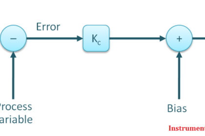
A forward acting controller has increasing output in response to an increasing measured variable.
A reverse acting controller has decreasing output in response to an increasing measured variable.
Empirical Tuning Method
Proportional only controller :
- With transfer switch at manual, set PB at maximum or at safe high value, usually 200% PB.
- Move transfer switch to auto and make changes in set point. The time required for the disturbance to settle
may then be noted. - Continue reducing band-width to half its previous value until the oscillation do not die away, But continue
to be perceptible. - Now increase the band-width to twice its value. This gives the required stability, that is, the minimum
stabilising time and minimum offset.
Proportional plus integral action
- Set the Integral Action Time (IAT) to maximum.- Adjust the proportional band as for a proportional controller.
- Decrease the IAT in steps, each step being such that line IAT 1s halved at each adjustment. Below some
critical value, depending upon the lag characteristics of the process, hunting will occur. This hunting Indicates
that the IAT has been reduced too far. - Now increase the time to approximately twice this value to restore the desired stability.
Proportional plus derivative action
- Adjust the Derivative Action Time (DAT) to its minimum value.
- Adjust the proportional band as described for proportional controller, but do not increase the band when hunting occurs.
- Increase the DAT (that is, double each setting) so that; the hunting caused by the narrow band is eliminated.
- Continue to narrow the band and again increase the DAT until the hunting is eliminated.
- Repeat previous step until further increase of the derivative action time fails to eliminate the hunting introduced by the reduction of the proportional band, or tends to increase it. This establishes the optimum value of the DAT and the hunting should be eliminated by increasing the width of the proportional band slightly.
Proportional plus integral plus derivative action
- Set IAT to a maximum.
- Set DAT to a minimum.
- Adjust the proportional band as for a P + D controller.
- Adjust derivative using same procedure as for above, P + D.-Adjust integral to a related value of the final derivative setting.
A three-term controller is therefore adjusted as for a P + D controller and the integral value simply related to thederivative value. In many cases, the setting procedure may be shortened by omitting settings, which are outside the probable range.
The process should then respond to set point or load changes, where integral action removes offset and the second overshoot of set point is approximately 1/4 the amplitude of the first.
This is commonly referred to asthe 1/4 decay method and is generally agreed to be the optimum controller setting for a P + I controller.
The above method is only used when no other controller setting data is available and must be practised with care.
Optimum Settings (Ultimate Method)
The closed loop or ultimate method involves finding the point where the system becomes unstable and using this as a basis to calculate the optimum settings.
The following steps may be used to determine ultimate PB and period:
- Switch the controller to automatic.
- Turn off all integral and derivative action.
- Set the proportional band to high value and reduce this value to the point where the system becomes unstableand oscillates with constant amplitude. Sometimes a small step change is required to force the system into itsunstable mode.
- The proportional band that required causing continuous oscillation is the ultimate value Bu.
- The ultimate periodic time is Pu.
- From these two values the optimum setting can be calculated.
- For proportional action only
PB% = 2 Bu % - Proportional + Integral
PB% = 2.2 Bu%
Integral action time = Pu / 1.2 minutes/repeat - Proportional + Integral + Derivative
PB%=1.67Bu
Integral action time = Pu / 2 minutes/repeatDerivative action = Pu / 8 minutes


Dear bharatwaj sir can you help me to know how to calculate kvar calculation as per load?
please I need details of complete Automation….