Inst ToolsInst ToolsInst Tools
  • Courses
  • Automation
    • PLC
    • Control System
    • Safety System
    • Communication
    • Fire & Gas System
  • Instrumentation
    • Design
    • Pressure
    • Temperature
    • Flow
    • Level
    • Vibration
    • Analyzer
    • Control Valve
    • Switch
    • Calibration
    • Erection & Commissioning
  • Interview
    • Instrumentation
    • Electrical
    • Electronics
    • Practical
  • Q&A
    • Instrumentation
    • Control System
    • Electrical
    • Electronics
    • Analog Electronics
    • Digital Electronics
    • Power Electronics
    • Microprocessor
  • Request
Search
  • Books
  • Software
  • Projects
  • Process
  • Tools
  • Basics
  • Formula
  • Power Plant
  • Root Cause Analysis
  • Electrical Basics
  • Animation
  • Standards
  • 4-20 mA Course
  • Siemens PLC Course
Reading: PID Block in RSLogix 500
Share
Font ResizerAa
Inst ToolsInst Tools
Font ResizerAa
  • Courses
  • Design
  • PLC
  • Interview
  • Control System
Search
  • Courses
  • Automation
    • PLC
    • Control System
    • Safety System
    • Communication
    • Fire & Gas System
  • Instrumentation
    • Design
    • Pressure
    • Temperature
    • Flow
    • Level
    • Vibration
    • Analyzer
    • Control Valve
    • Switch
    • Calibration
    • Erection & Commissioning
  • Interview
    • Instrumentation
    • Electrical
    • Electronics
    • Practical
  • Q&A
    • Instrumentation
    • Control System
    • Electrical
    • Electronics
    • Analog Electronics
    • Digital Electronics
    • Power Electronics
    • Microprocessor
  • Request
Follow US
All rights reserved. Reproduction in whole or in part without written permission is prohibited.
Inst Tools > Blog > PLC Tutorials > PID Block in RSLogix 500

PID Block in RSLogix 500

Last updated: March 4, 2021 11:58 am
Editorial Staff
PLC Tutorials
No Comments
Share
6 Min Read
SHARE

In this article, I will cover the PID block in RSlogix 500 with an example of process control.

This is an output instruction that controls physical properties such as temperature, pressure, liquid level, or flow rate using process loops.

PID closed-loop control holds a process variable at the desired set point.

The PID equation controls the process by sending an output signal to the control valve. The greater the error between the setpoint and process variable input, the greater the output signal, and vice versa.

The PID algorithm is used to control an analog process having a single control point and a single feedback signal. The PID algorithm controls the output to the control point so that a setpoint is achieved. The setpoint may be entered as a static variable or as a dynamic variable that is calculated from a mathematical operation.

PID Controllers are generally available in two types. One is a Single-stand-alone microcontroller-based hardware controller unit. The second one is as a software block in PLC or DCS programming.

To understand the PID block (software) in RSlogix software follows the below steps.

Step 1:

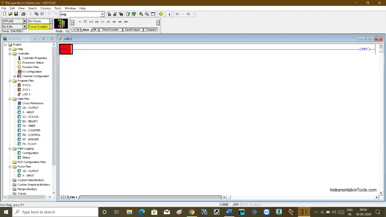
Open RSlogix 500. Create a new project and open programming environment.

Download RsLogix 500 if you don’t have it.

Open RSlogix 500

Step 2:

Let’s consider the process where I have to control the flow of fluid.

For that, I have a flow transmitter that provides me the present flow rate (feedback), a controller (PID block) which compares with the setpoint and present flow rate, then PID controls the manipulated variable (control valve) to maintain the required flow rate as per setpoint.

Step 3:

To do that, I need two Scale with Parameter (SCP) instructions. One SCP instruction will convert the value of the flow transmitter (4-20 mA) to raw value and another SCP instruction will convert a raw value to 4-20 mA (control valve).

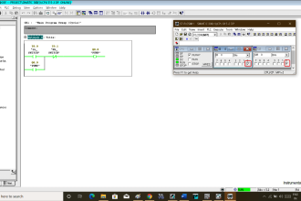
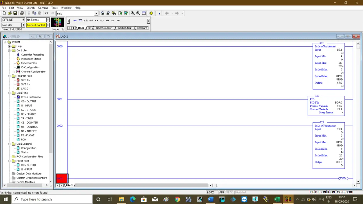
Following is the program, in the first rung I have used SCP instruction which has input coming from the flow transmitter (I0:1).

Input minimum and maximum are 4mA and 20mA respectively. I have scaled it for raw value from 0 to 8192 counts as I have considered a resolution of 12 bit for my analog input card.

The output of the scaled input will store to a memory location (N7:0).

In the second rung, the PID block is used where I have a process variable (flow rate). I have given the address of input which I have scaled and a control variable address (N7:1) which represents the control valve memory address.

In the third rung, I have scaled the raw value to 4 to 20 mA signal to operate the valve.

RSLogix 500 PID block

For example, I have the following condition

SP (setpoint) : 12 m3/hr

PV (Input coming from the transmitter – flow rate): 12 m3/hr

MV (Control valve output) : 50 %

If I changed the setpoint or process variable value change from 12m3/hr to 11 m3/hr, then the controller compares it with a setpoint and produces an error. The PID changes the manipulated variable based on the error, then fed to the control valve to open/close the valve until the process reaches its flowrate as per the required setpoint.

Step 4:

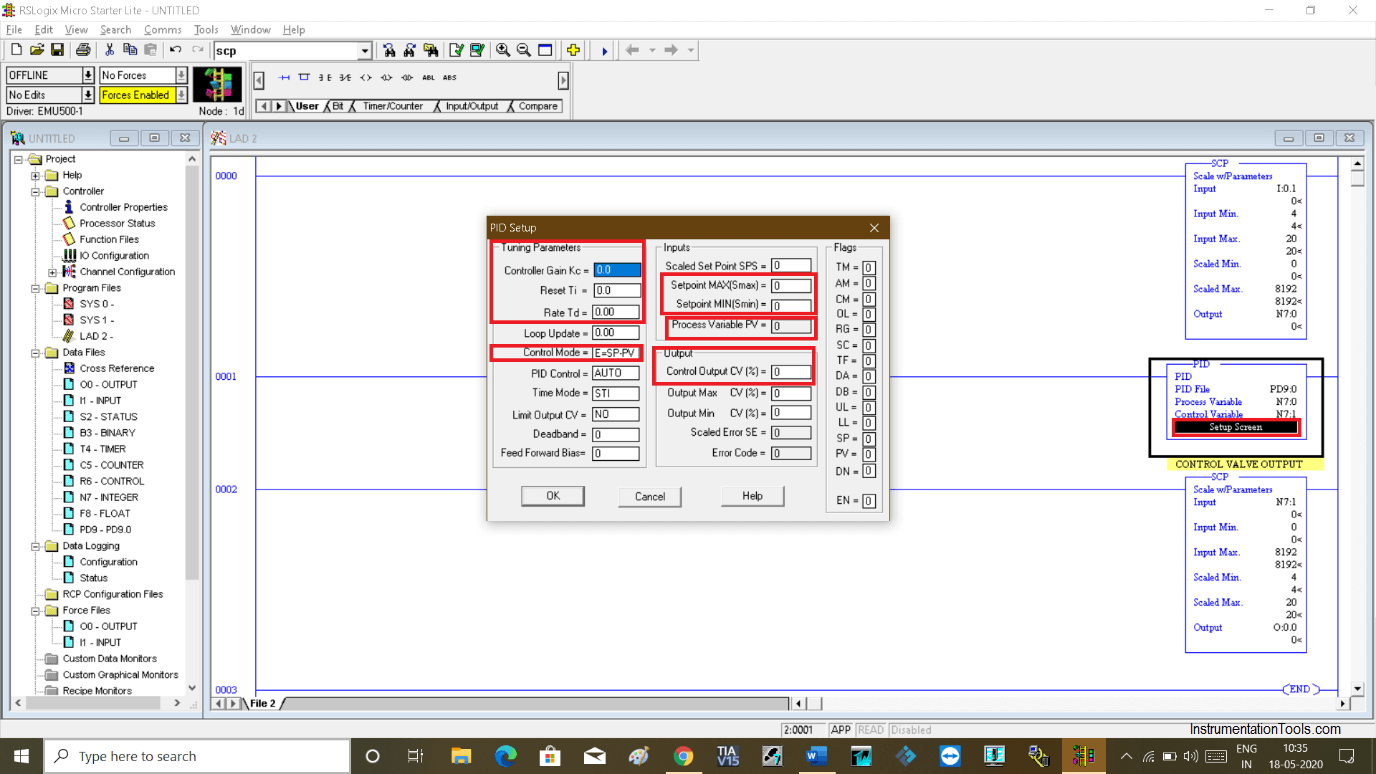
To set all the value, Double click “setup screen” on the PID block. The following window will pop-up as shown in below.

You can set all the required values from this window. You can tune the controller.

PID Block in RSLogix 500

As RSlogix won’t allow running a PID block with an emulator, I can not show you by running the logic. But, this is the best way to understand how logic works.

Step 5:

When you add PID block to the rung and compile it. You receive an error. To solve this, we have to define a PID block.

To do that, on the left side right click on “data file” and click on “new”.
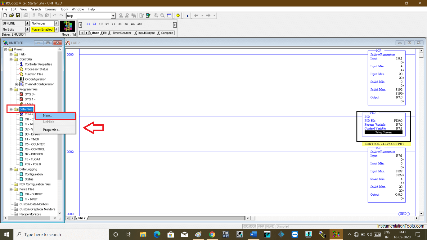
PID Programming Using RSLogix 500

Step 6:

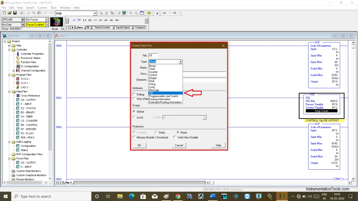
The following window will pop-up.

In the “type” section, select PID and define the name. Click “ok” and you are done with PID block data type.

RSLogix 500 PID instruction

Author: Suhel Patel

If you liked this article, then please subscribe to our YouTube Channel for PLC and SCADA video tutorials.

You can also follow us on Facebook and Twitter to receive daily updates.

Read Next:

  • FIFO Instruction in AB PLC
  • Allen Bradley Powerflex VFD
  • Analog Input in RSLogix 500
  • Free CODESYS HMI software
  • Namur Digital Input Card
Don't Miss Our Updates
Be the first to get exclusive content straight to your email.
We promise not to spam you. You can unsubscribe at any time.
Invalid email address
You've successfully subscribed !

Continue Reading

Industrial Automation and Control Systems (IACS)
Key Facts About RS485 Industrial Network
Connect to the Siemens S7 PLC
Difference between Timer and Counter – PLC Basics
Chemical Mixing Process using PLC
PLC based Metro Automation Project
Share This Article
Facebook Whatsapp Whatsapp LinkedIn Copy Link
Share
Leave a Comment

Leave a Reply Cancel reply

Your email address will not be published. Required fields are marked *

Stay Connected

128.3kFollowersLike
69.1kFollowersFollow
210kSubscribersSubscribe
38kFollowersFollow

Categories

Explore More

What are Functions in PLC Programming? (FCs)
Machine Indicator Lights: PLC Programming Solution
Transmitters 4-20mA Current Failure Alarm Limits
Steps in PLC System Design
Working Principle of Single Phase Preventer Relay
PLC Multiple Outputs Configuration
Siemens PLC Comparator Logic
PLC Automatic Door Control System – Programming Example

Keep Learning

PLC Cabinet

PLC Programming Videos

PLC and MCC Panel Interface Design

PLC Panel and MCC Panel Interface Signals

PLC Program to Count and Pack Parts from conveyor

Count and Pack Objects from Conveyor using PLC Ladder Logic

Sequential Operation of Output Bits using Two Push buttons

Sequential Operation of Output Bits using Two Push buttons

Example Ladder Logic Diagram

What is Relay Logic ?

Program to implement T Flip Flop logic

T Flip Flop PLC Ladder Diagram

PLC Batch System for 4 Tanks Mixing using CX-Programmer

PLC Batch System for 4 Tanks Mixing using CX-Programmer

Timer-based vacuum cleaner in Schneider PLC

Schneider Electric PLC Timer Problem: Vacuum Cleaner

Learn More

PLC Programming Basics for a Packing Machine Control System

PLC Packing Machine Control System Program in XG5000

LED Projects for Engineering Students

LED Projects for Engineering Students

Why Calibration is Important

Why Calibration is Important?

HART-IP Principle

What is HART- IP ?

Sugar Plant - Automatic Control of Massecuite Feed

Sugar Plant – Automatic Control of Massecuite Feed

Parallel Circuit Parallel Current Calculations

Parallel Circuit Current Calculations

Convert-Process-Variable-to-Percentage

Convert Process Variable to Percentage

Digital Electronics Multiple Choice Questions

Ripple Counter Objective Questions

Menu

  • About
  • Privacy Policy
  • Copyright

Quick Links

  • Learn PLC
  • Helping Hand
  • Part Time Job

YouTube Subscribe

Follow US
All rights reserved. Reproduction in whole or in part without written permission is prohibited.
Welcome Back!

Sign in to your account

Username or Email Address
Password

Lost your password?