Inst ToolsInst ToolsInst Tools
  • Courses
  • Automation
    • PLC
    • Control System
    • Safety System
    • Communication
    • Fire & Gas System
  • Instrumentation
    • Design
    • Pressure
    • Temperature
    • Flow
    • Level
    • Vibration
    • Analyzer
    • Control Valve
    • Switch
    • Calibration
    • Erection & Commissioning
  • Interview
    • Instrumentation
    • Electrical
    • Electronics
    • Practical
  • Q&A
    • Instrumentation
    • Control System
    • Electrical
    • Electronics
    • Analog Electronics
    • Digital Electronics
    • Power Electronics
    • Microprocessor
  • Request
Search
  • Books
  • Software
  • Projects
  • Process
  • Tools
  • Basics
  • Formula
  • Power Plant
  • Root Cause Analysis
  • Electrical Basics
  • Animation
  • Standards
  • 4-20 mA Course
  • Siemens PLC Course
Reading: Parallel Short Circuit Faults
Share
Notification Show More
Font ResizerAa
Inst ToolsInst Tools
Font ResizerAa
  • Courses
  • Design
  • PLC
  • Interview
  • Control System
Search
  • Courses
  • Automation
    • PLC
    • Control System
    • Safety System
    • Communication
    • Fire & Gas System
  • Instrumentation
    • Design
    • Pressure
    • Temperature
    • Flow
    • Level
    • Vibration
    • Analyzer
    • Control Valve
    • Switch
    • Calibration
    • Erection & Commissioning
  • Interview
    • Instrumentation
    • Electrical
    • Electronics
    • Practical
  • Q&A
    • Instrumentation
    • Control System
    • Electrical
    • Electronics
    • Analog Electronics
    • Digital Electronics
    • Power Electronics
    • Microprocessor
  • Request
Follow US
All rights reserved. Reproduction in whole or in part without written permission is prohibited.
Inst Tools > Blog > Electrical Theory > Parallel Short Circuit Faults

Parallel Short Circuit Faults

Last updated: July 25, 2018 8:30 pm
Editorial Staff
Electrical Theory
No Comments
Share
1 Min Read
SHARE

Faults within a DC circuit will cause various effects, depending upon the nature of the fault. An understanding of the effects of these faults is necessary to fully understand DC circuit operation.

Parallel Short Circuit

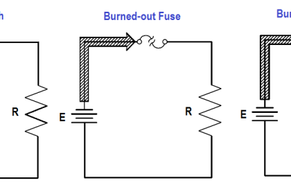
When a parallel circuit becomes short circuited, the same effect occurs as in a series circuit: there is a sudden and very large increase in circuit current (Figure 57).

Shorted Parallel Circuit

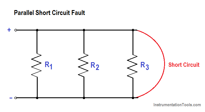
Figure 57 : Shorted Parallel Circuit

Parallel circuits are more likely than series circuits to develop damaging short circuits. This is because each load is connected directly across the power source. If any of the load becomes shorted, the resistance between the power source terminals is practically zero. If a series load becomes shorted, the resistance of the other loads keeps the circuit resistance from dropping to zero.

Don't Miss Our Updates
Be the first to get exclusive content straight to your email.
We promise not to spam you. You can unsubscribe at any time.
Invalid email address
You've successfully subscribed !

Continue Reading

Schematic Diagram
Apparent Power, True Power, Reactive Power & Total Power
DC Generator Internal Losses
Power Factor Meter Principle
High Voltage Circuit Breaker Principle
Voltage and Current Phase Relationships in an Inductive Circuit
Share This Article
Facebook Whatsapp Whatsapp LinkedIn Copy Link
Share
Leave a Comment

Leave a Reply Cancel reply

Your email address will not be published. Required fields are marked *

Stay Connected

128.3kFollowersLike
69.1kFollowersFollow
210kSubscribersSubscribe
38kFollowersFollow

Categories

Explore More

Starting a Synchronous Motor
Transformer Impedance Ratio
Unbalanced 3 Phase Loads
Transformer Current Ratio
Transformer Turns Ratio
Low Voltage Protection (LVP) and Low Voltage Release (LVR)
Shunt-Wound DC Generators
Capacitive Time Constant

Keep Learning

Basic AC Generator

AC Generator Parts

Electrical Component Symbols

Electrical Diagrams and Schematics

induction motor torque versus speed

Induction Motor Torque Versus Slip

current division Formula for Resistor Circuit

Current Division

3-Wire, Three-Phase Delta Wiring System

3-Wire, Three-Phase Delta Wiring System

Wattmeter Principle

Wattmeter

Inductor Principle

Inductance and Inductive Reactance

Total Resistance in a Parallel Circuit

Resistance in Parallel Circuits

Learn More

What is PID Controller

What is PID Controller?

What is Partial Stroke Test

What is Partial Stroke Test?

Fail Safe Switch Circuit

Basics of Fail-safe Circuits

Total Resistance in a Parallel Circuit

Resistance in Parallel Circuits

Power Electronics Objective Questions

Harmonic Reduction Objective Questions

Solenoid Valves Questions

Solenoid Valves Questions & Answers – 3

Electrical Machines Questions and Answers

Induction Machines Equivalent Circuit Parameters

Changing Process Medium Density has no influence on Level Indication (Full Absorption)

Nuclear Interface Level Measurement Principle, Limitations, Installation and Calibration

Menu

  • About
  • Privacy Policy
  • Copyright

Quick Links

  • Learn PLC
  • Helping Hand
  • Part Time Job

YouTube Subscribe

Follow US
All rights reserved. Reproduction in whole or in part without written permission is prohibited.
Welcome Back!

Sign in to your account

Username or Email Address
Password

Lost your password?