The technique which supports the measurement of temperature of the objects without touching them is called as pyrometric measurement .This is a non contact type measurement which is being used in various industrial application.
Pyrometer
A pyrometer is a device that is used for the temperature measurement of an object. The device actually tracks and measures the amount of heat that is radiated from an object. The thermal heat radiates from the object to the optical system present inside the pyrometer. The optical system makes the thermal radiation into a better focus and passes it to the detector. The output of the detector will be related to the input thermal radiation. The biggest advantage of this device is that, unlike a Resistance Temperature Detector (RTD) and Thermocouple, there is no direct contact between the pyrometer and the object whose temperature is to be found out.
Basic principle
The object whose temperature is above absolute zero (i.e.273.15 K) emits or generates radiation .The emission is heat radiation which depends on temperature.Generally the infrared radiation is referred to the measurement type as majority of radiations lie in the electromagnetic spectrum of infrared domain.This domain lies in the spectrum of above visible red light.The energy radiated by the object is used to measure the temperature of the object through the use of detective device which converts the received signal in to electrical signal.The instruments or systems which is used for measurement purpose is known by common names such as pyrometer/temperature guns or radiation pyrometers .
Optical Pyrometer
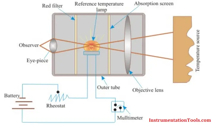
In an optical pyrometer, a brightness comparison is made to measure the temperature. As a measure of the reference temperature, a color change with the growth in temperature is taken. The device compares the brightness produced by the radiation of the object whose temperature is to be measured, with that of a reference temperature. The reference temperature is produced by a lamp whose brightness can be adjusted till its intensity becomes equal to the brightness of the source object. For an object, its light intensity always depends on the temperature of the object, whatever may be its wavelength. After adjusting the temperature, the current passing through it is measured using a multimeter, as its value will be proportional to the temperature of the source when calibrated. The working of an optical pyrometer is shown in the figure below.
Also See: Optical pyrometer Animation
As shown in the figure above, an optical pyrometer has the following components.
- An eye piece (observer) at the left side and an optical lens on the right.
- A reference lamp, which is powered with the help of a battery.
- A rheostat to change the current and hence the brightness intensity.
- So as to increase the temperature range which is to be measured, an absorption screen is fitted between the optical lens and the reference bulb.
- A red filter placed between the eye piece and the reference bulb helps in narrowing the band of wavelength.
Working
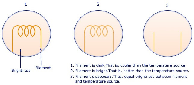
The radiation from the source is emitted and the optical objective lens captures it. The lens helps in focusing the thermal radiation on to the reference bulb. The observer watches the process through the eye piece and corrects it in such a manner that the reference lamp filament has a sharp focus and the filament is super-imposed on the temperature source image. The observer starts changing the rheostat values and the current in the reference lamp changes. This in turn, changes its intensity. This change in current can be observed in three different ways.
1. The filament is dark. That is, cooler than the temperature source.
2. Filament is bright. That is, hotter than the temperature source.
3. Filament disappears. Thus, there is equal brightness between the filament and temperature source. At this time, the current that flows in the reference lamp is measured, as its value is a measure of the temperature of the radiated light in the temperature source, when calibrated.
Advantages
- Simple assembling of the device enables easy use of it.
- Provides a very high accuracy with +/-5 degree Celsius.
- There is no need of any direct body contact between the optical pyrometer and the object. Thus, it can be used in a wide variety of applications.
- As long as the size of the object, whose temperature is to measured fits with the size of the optical pyrometer, the distance between both of them is not at all a problem. Thus, the device can be used for remote sensing.
- This device can not only be used to measure the temperature, but can also be used to see the heat produced by the object/source. Thus, optical pyrometers can be used to measure and view wavelengths less than or equal to 0.65 microns. But, a Radiation Pyrometer can be used for high heat applications and can measure wavelengths between 0.70 microns to 20 microns.
- Can measure the moving objects.
- Electrical items temp. can be measured which is very critical if we think of contact type measurement expl HT panels,transformers.
- The instruments can be used where physical approach is difficult Small ducts or some object at roof heights.
Disadvantages
- As the measurement is based on the light intensity, the device can be used only in applications with a minimum temperature of 700 degree Celsius.
- The device is not useful for obtaining continuous values of temperatures at small intervals.
Applications
- Used to measure temperatures of liquid metals or highly heated materials.
- Can be used to measure furnace temperatures.
Article Written by:
Pravin V. Maheshkar
Pune
7023204432