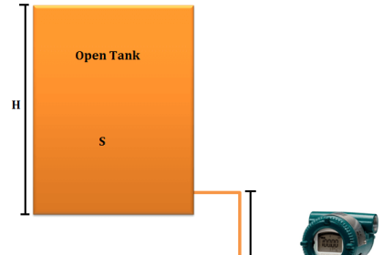
Open Tank Interface Level Measurement
Interface level can be measured in a vessel or tank using differential pressure transmitter or pressure transmitter.
An interface level measurement is only possible if the densities of the two products in the tank/vessel remains same.
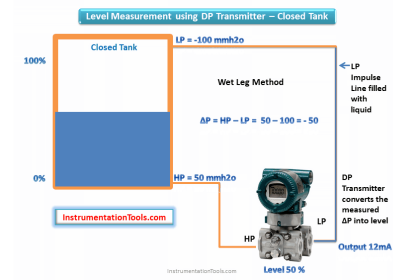
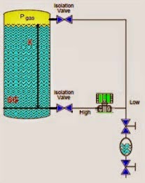
if we are using DP Transmitter then the HP side is connected to the tank tapping point and LP side is vent to atmosphere or we can use a pressure transmitter also.
The DP Transmitter calibration parameters will vary depending on installation & seal system also. Generally we can see three possibilities of installation of a transmitter in the field.
They are :
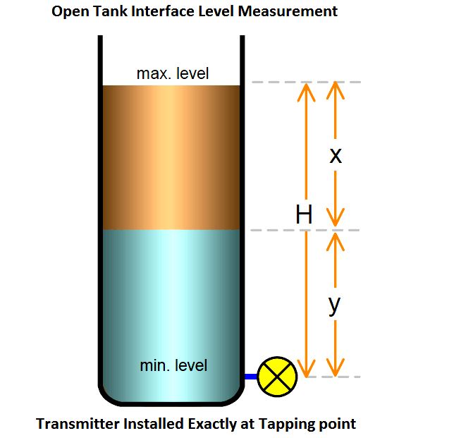
- Transmitter installed Exactly at tapping point ( Ideal & preferred way of installation)
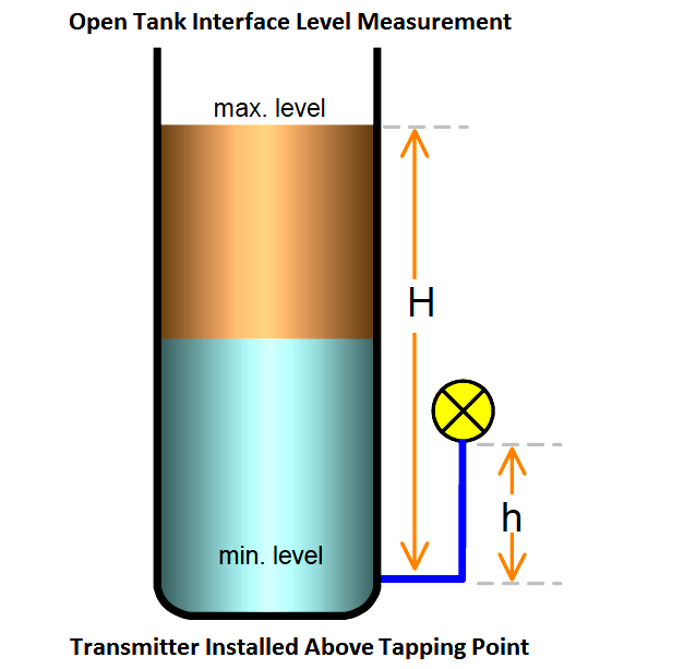
- Transmitter installed above tapping point ( Not preferable, Chance of bubble formation in the impulse line)
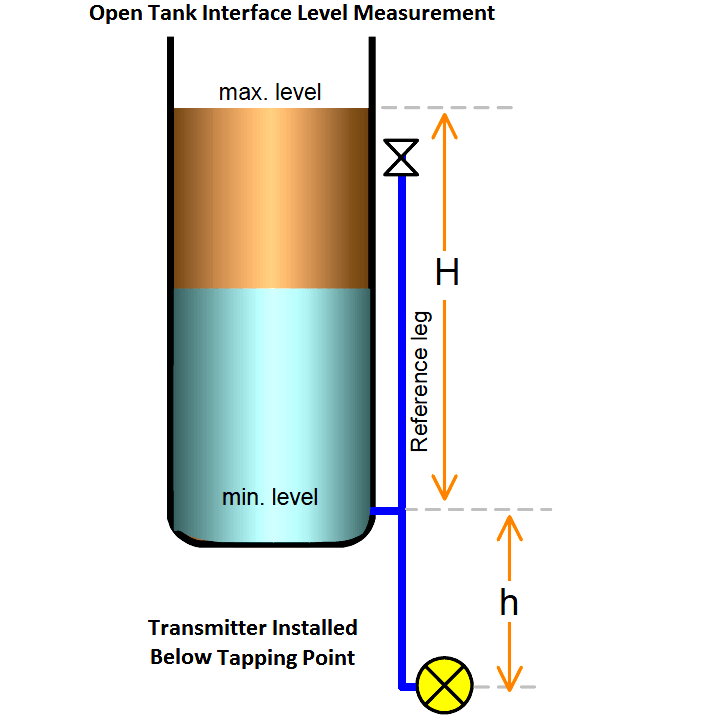
- Transmitter installed below tapping point (Error can be compensated effectively)
So we have to calibrate the transmitter depending on the type of installation in the field. The calibration formula will vary slightly depending on the installation.Every transmitter have two important parameters, they are Lower Range Value (LRV) & Upper Range Value (URV). We have to calculate the LRV & URV values based on type of installation. The below figures with formulas dictates the calculations. After calculating the values, configure the same parameters in the transmitter using HART communicator.
Here we are discussing two types of seal systems : with seal & without seal,
- With Seal System : The impulse line is filled with special fluid like with glycerine, glycol etc
- Without Seal System : Tank / Vessel fluid will be filled with the impulse lines
Normal installation (transmitter mounted leveled with the tapping point)
With seal system;
LRV = ρu • g • H , or,
LRV = (SGu • H)
URV = ρl • g • H , or,
URV = (SGl • H)
Without seal system;
(assume the leg is always filled with lower liquid)
LRV = ρu • g • H , or,
LRV= (SGu • H)
URV = ρl • g • H
URV = (SGl • H)
Elevated-Zero installation (transmitter mounted above the tapping point)
With seal system;
Zero Elevation = − (ρf • g • h)
Min. Head = ρu • g • H , or, = (SGu • h)
Span = ρl • g • H , or, = (SGl • h)
Without seal system;
Not preferable
Therefore, for calibration;
4mA (LRV) = Min. Head + Zero Elevation
20mA (URV) = Span + Zero Elevation
Suppressed-Zero installation (transmitter mounted below the tapping point)
With seal system;
Zero Suppression = ρf • g • h
Min. Head = ρu • g • H , or, = (SGu • h)
Span = ρl • g • H , or, = (SGl • h)
Without seal system;
Zero Suppression = ρl • g • h
Min. Head = ρu • g • H , or, = (SGu • h)
Max. Head or Span = ρl • g • H
Therefore, for calibration;
4mA (LRV) = Min. Head + Zero Suppression
20mA (URV) = Span + Zero Suppression
NOTE:
ρp = density of process liquid in the tank
ρf = density of fill-liquid in the tubing
ρu = density of upper liquid
ρl = density of lower liquid
SGp = std. gravity of process liquid.
SGf = std. gravity of fill liquid
SGu = std. gravity of upper liquid
SGl = std. gravity of lower liquid
Article Source : N. Asyiddin